background image

6

7

INSTALLATION AND OPERATION MANUAL SOLAR MODULES GENERATION 4 (G4.1) – HANWHA Q CELLS AUSTRALIA PTY LTD – EN

INSTALLATION AND OPERATION MANUAL SOLAR MODULES GENERATION 4 (G4.1) – HANWHA Q CELLS AUSTRALIA PTY LTD – EN

Installation Site

Please note the following guidelines that apply to the 
installation site:

• 

The modules have been tested according to IEC 61215 
for operation in a temperate climate.

• 

Solar modules are not explosion-proof and are not suitable 
for use in explosive environments.


Ä

Do not operate solar modules near highly flammable gas 
and vapors (e.g. gas tanks, gas stations).


Ä

Do not install modules in enclosed space.


Ä

Do not install modules in locations where they may be 
submerged in water for lengthy periods (e.g. floodplains).


Ä

Do not use modules as a substitute for the normal 
roofing (e.g. modules are not rainproof).


Ä

Do not install modules in close proximity to air conditioning 
systems

The solar modules are designed for the following applica-
tions:

• 

Operating temperatures from –40 °C to +85 °C  
(–40 °F to +185 °F). 

• 

Wind loads up to max. 4,000 Pa and snow loads up 
to max. 5,400 Pa (Test-load in accordance with IEC 
61215, see chapter 2.3 mounting options).

• 

Installation using a mounting frame for solar modules.

Prevention of Shadowing Effects

Optimal  solar irradiation leads to maximum energy output:


Ä

For this reason, install the modules so that they face 
the sun. 


Ä

Avoid shadowing  (due to objects such as buildings, 
chimneys or trees). 


Ä

Avoid partial shading (for example through overhead 
lines, dirt, snow).

Mounting Frame Requirements

The Modules shall be installed and operated on mounting 
frames that comply with any applicable laws and stipula-
tions as well as with the following:

• 

Conform to the necessary structural requirements.

• 

Compliant with local snow and wind loads.

• 

Properly fastened to the ground, the roof, or the façade.

• 

Forces acting on the module are relayed to the mounting 
substructure.

• 

Ensures sufficient rear ventilation of the module.

• 

Guarantees long-term stability. 

• 

Avoid the usage of different metals to prevent contact 
corrosions.

• 

Allows for stress-free expansion and contraction due to 
temperature fluctuations.


Ä

Ensure that no mechanical stresses (e.g., caused by vibrations, 
twisting, or expansion) are generated on the module. 


Ä

Ensure that the clamps and the mounting frame are 
compatible.

Clamp System Requirements

Use customary clamps that satisfy the following require-
ments:

• 

Clamp width: 

 40  mm.

• 

Clamp height compliant with a 32 mm frame height.

• 

Clamp depth: 7–12 mm.

• 

Clamps are not in contact with the front glass.

• 

Clamps do not deform the frame.

• 

Clamps that satisfy the structural requirements of the 
installation site.

• 

Long-term stable clamps that securely affix the module 
to the mounting frame.

Module Orientation Requirements

• 

Vertical or horizontal installation is permitted.


Ä

Ensure that rain and melting snow can run off freely. 
No water accumulation.


Ä

Ensure that the drainage holes in the frame are not 
covered. No sealing.


Ä

Maintain the permissible angle of 
inclination.

• 

Minimum angle of inclination: 3°

• 

Maximum angle of inclination: 75°

• 

Follow the directions for installation 
angles < 5° (“Grounding”, p. 18)

75°

2.2  Requirements

2 PLANNING

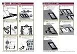
Fig. 2: 

Installation options for crystalline Q CELLS modules. All dimensions are given in mm. Also observe the  


allowed static loads and clamping range as specified on the following page. 


The illustrated installation options apply for both horizontal and vertical module orientation. 


Module 

Clamp 

Subconstruction 

Mounting profile

2.3  Mounting options

2 PLANNING

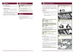
TYPE OF 
INSTALLATION

MODULE

POINT MOUNTING SYSTEM

LINEAR MOUNTING SYSTEM

INSTALLATION 
WITH  
CLAMPS

Q.PRO-G4.1
Q.PLUS-G4.1

HYBRID CLAMPING

Q.PRO-G4.1
Q.PLUS-G4.1

INSTALLATION  
ON MOUNTING  
POINTS

Q.PRO-G4.1
Q.PLUS-G4.1

INSTALLATION 
WITH  
INSERTION  
PROFILES

Q.PRO-G4.1
Q.PLUS-G4.1

NOT PERMITTED

CL3

CL4

250 - 450

150 - 350

0 - 300

0 - 300

CL3

CL4

CL4

0 - 200

CL1

250 - 450

150 - 350

CL1

345

274

FB2

EN

4 × Fastening 
points

4 × Fastening 
points

FB2

EN

345

4 x Fastening 
points

274

4 x Fastening 
points

FB1

FB1

300 - 400

0 - 100

CL5

0 - 100

CL2

0 - 100

CL2

IP1

IP2

IP1

IP2

Summary of Contents for Q.PLUS-G4.1

Page 1: ...Valid for Australia and New Zealand Q PRO G4 1 Q PLUS G4 1 INSTALLATION AND OPERATION MANUAL ...

Page 2: ...ions In particular the installer as well as the operator of a module is responsible for compliance with all applicable statutory requirements and regulations Ä Ä Unless otherwise specified by any laws or regulations the following stipulations must be upheld at all times during the installation operation and maintenance of the solar modules This manual Other applicable stipulations such as country ...

Page 3: ...ety regulations during set up and installation Q CELLS assumes no liability on the basis of these instructions Q CELLS is only liable in the context of contractual agreements or in the context of accepted guarantees Q CELLS accepts no other responsibility for the functionality and safety of the modules Ä Ä Please observe the instructions for any other sys tem components that may be part of the com...

Page 4: ...entilation of the module Guarantees long term stability Avoid the usage of different metals to prevent contact corrosions Allows for stress free expansion and contraction due to temperature fluctuations Ä Ä Ensure that no mechanical stresses e g caused by vibrations twisting or expansion are generated on the module Ä Ä Ensure that the clamps and the mounting frame are compatible Clamp System Requi...

Page 5: ...election For detailed key electrical data please refer to the actual data sheet referring to the relevant Module available at www q cells com Ä Ä Only connect modules of the same type and power class Safety Factor During normal operation a module may generate a greater current and or higher voltage than that determined under standardised test conditions Please use a safety factor of 1 25 for the f...

Page 6: ...modules securely in cool and dry rooms The packaging is not weatherproof DANGER Risk of fatal injury due to electric shock Ä Ä Do not install damaged modules Ä Ä Inform your distributor of any damages immediately 3 1 Safety and transport 3 INSTALLATION NOTE Module damage may occur Ä Ä Never lift or move the module with the connection cables or junction box Ä Ä Carry modules upright and horizontall...

Page 7: ...indy or wet weather DANGER Risk of fatal injury due to electric shock Ä Ä Only use dry insulated tools Ä Ä Do not carry out the installation alone Only install undamaged modules and components Ä Ä Do not modify the module e g do not drill any additional holes 3 2 Preparation of installation 3 INSTALLATION Ä Ä Maintain an interval of at least 10 mm between two modules 10mm 1 0 m m Option 2 Ä Ä Inst...

Page 8: ...re disconnected at the inverter prior to separation Ä Ä Be sure to observe the specified time intervals after switching off the inverter High voltage components need time to discharge DANGER Risk of fatal injury due to electric shock Ä Ä Never open the junction box Ä Ä Change of bypass diodes is only allowed by qualified and trained personnel in disconnected and covered state DANGER Risk of fatal ...

Page 9: ...c shock Ä Ä Ensure that all electrical components are in a proper dry and safe condition Ä Ä Standard wiring with a return cable Inverter EN 4 3 Connection of modules 4 ELECTRICAL CONNECTION Ä Ä Ensure that all necessary safety and functional tests have been carried out according to current industry standards NOTE Module damage may occur Ä Ä Ensure that the plug connections are secured away from a...

Page 10: ... performance Maintenance Ä Ä The system should be inspected by an installer annually to check the following all system components sit securely and are corrosion free the connection is secure and all electrical components are clean and undamaged Cleaning WARNING Risk of injury due to hot and live modules Ä Ä Only clean modules that have cooled down Ä Ä Do not carry or wear any electrically conducti...

Page 11: ...D Level 14 20 Berry Street North Sydney NSW 2060 TEL 61 0 2 9016 3033 FAX 61 0 2 9016 3032 EMAIL service q cells com au WEB www q cells com au Subject to change without notice Hanwha Q CELLS Installation manual G4 1 modules_2016 02_Rev02_EN ...

Reviews: