


8
LGW/L
GB
Instructions for installation and use
The air-curtain unit is intended for permanent
mounting above entrance doors and small doors
up to a height of 3 metres. The unit can also be
used for industrial heating and drying
applications. The low built-in depth as well as the
frontal position of the air intake allows the unit to
be fitted where the space between the roof and
the top edge of the door opening is limited.
However, bear in mind the water connections on
the top of the unit. The unit can also be built into
suspended ceilings. The optimal curtain effect is
obtained when the unit covers the entire
opening.
Installation
The unit may only be mounted horizontally with
the exhaust opening facing downwards. Where
openings are wide several units can be mounted
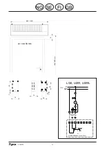
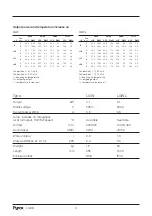
side by side. For other measurements and mini-
mum installation distances, see Fig. on page 3.
1.
Mounting on a wall or beam
A: Suspend from the two keyhole slots on
the rear of the unit. Suitable screws are
M6S M6, Superteks HB ST 6.3 or T6S
(French wood screws). NOTE! When using
the keyhole slots the unit must be secured
with the supplied safety strip. The strip can
be fitted facing upwards or downwards.
B: Bolted to a wall or beam. Four M6 blind
nuts on the rear of the unit are provided for
this type of mounting.
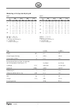
2.
Suspended from roof hangers
Four blind nuts located on top of the unit
are provided for suspending from roof
hangers. Spacing in pairs c/c distance 100
mm. See the measurement diagram.
Brackets for roof suspension are available
as an accessory, order no. 22 005.
Electrical installation LGW/L
Electrical connections to the fan motor are made
using a cable fitted with a plug which is
connected to an appropriate 220V wall socket.
There are a number of knock-outs located on
top of the unit for cable entry. Connection of the
control panel may only be carried out by a
qualified electrician.
Water connection LGW/L
The pump hot water is connected via the top of
the unit to two couplings with R15 internal
threads. The plug for draining the water is placed
in the coupling area on the lower section of the
inlet pipe. The coupling area is accessible after
removing the front grille.
NOTE! Work in the coupling area may only be
carried out by qualified personnel. All electrical
wiring must be disconnected before
commencing work. No water must come into
contact with electrical parts.
Control panel (ordered separately)
A single control panel may control up to four air
curtains. The control panel is supplied in a
separate plastic case, but may be built into the
air curtain instead:
1
Remove the intake grille, filter and the cover
plate from the connection compartment.
2
Remove the right hand endplate from the air
curtain.
3
Remove the cover from the underside of the
air curtain at the right hand edge.
4
Remove the cover from the control box.
5
Unscrew the control panel out of its box.
Connect the supplied leads to the terminal
block on the panel, see wiring diagram.
6
Install the panel in the curtain.
7
Connect the leads to the air curtain terminal
block, see wiring diagram.
Cleaning
The front grille and filter should be cleaned
regularly. A suitable interval is when the grille
appears to be dirty. Switch off the current, wipe
the front grille using a damp cloth, unscrew the
grille, remove the dust filter and wash. If the filter
is very clogged it may be necessary to replace it.
Order no. F83153 or F831524 respectively.