background image

Rins 181 Issue7 


    Page 31 

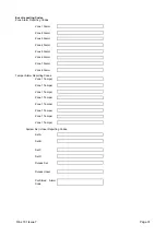
Event reporting Codes


Zone Alarm Reporting Codes. 


Zone 1 Alarm 


Zone 2 Alarm 


Zone 3 Alarm 


Zone 4 Alarm 


Zone 5 Alarm 


Zone 6 Alarm 


Zone 7 Alarm 


Zone 8 Alarm 


Tamper Alarm Reporting Codes. 

Zone 1 Tamper 


Zone 1 Tamper 


Zone 1 Tamper 


Zone 1 Tamper 


Zone 1 Tamper 


Zone 1 Tamper 


Zone 1 Tamper 


Zone 1 Tamper 


System Set / Unset Reporting Codes. 


Set A 


Set B 


Set C 


Set D 


Duress Set 


Duress Unset 


Confirmed Alarm 
Code 


Summary of Contents for BUMBT!8

Page 1: ...NSTRUCTIONS LED Remote Keypad Pyronix Ltd October 2001 This Product is approved for use in the Residential Commercial and Light Industrial Environment 8 A B C D 2 1 3 4 SET 5 6 7 8 9 0 INSTALLER DETAILS TELEPHONE X X X X X X X X A B C D OR ...

Page 2: ... specifications without giving prior notice A copy of our warranty can be obtained from the above address Pyronix Limited Pyronix House Braithwell Way Hellaby Rotherham S66 8QY ENGLAND Tel 44 0 1709 700100 Fax 44 0 1709 533429 Technical help line UK only 0900 8037 800 email export sales pyronix com marketing pyronix com technical support pyronix com website www pyronix com This is a premium rate l...

Page 3: ...ephone Connections 16 10 8 Powering Up The panel 16 10 9 Atlas End of Line Wiring Diagram 17 10 10 Atlas Double Pole Wiring Diagram 18 11 PROGRAMMING 19 11 1 Factory Defaults 19 11 2 Entering Engineer Mode 19 11 3 Setting Volume Control 19 11 4 Resetting The Non Volatile Memory NVM to Factory Settings 19 11 5 Setting The Panel When Mains Fails 20 11 6 Programming Set Modes 20 11 7 Setting The Alar...

Page 4: ...s 25 11 11 19Digicom Codes 26 11 11 20Keyswitch Set Configuration 26 11 11 21Group Reporting Telephone Allocation 26 11 11 22Engineer NVM Reset 26 11 11 23Follow Select 26 11 11 24Exiting Engineer Mode 26 12 SYSTEM FAULTS 27 13 TECHNICAL SPECIFICATION 28 13 1 Power supply 28 13 2 Control PCB 28 13 3 Mechanical 28 13 4 Environmental 28 13 5 Cleaning 28 14 ENGINEER QUICK REFERENCE PROGRAMMING 29 15 ...

Page 5: ...ility 2 Event log viewing 3 2 Master User Manager User All Limited User facilities 3 Clearing of event log if allowed by the Engineer 4 Alteration of both Limited and Master User codes the Manager cannot alter the Master User Code 5 LED Strobe Bell Extension Speaker test facility 6 Walk test facility for all four set modes 7 Programmable output operations 8 Remote Dial in enabling 3 3 Engineer All...

Page 6: ...t and an Access zone is triggered before an Entry Exit zone then an alarm will be generated immediately Immediate This is a zone which will when entered create an alarm when the panel is set Omit If a zone is programmed as an Omitted zone by the Engineer then it is ignored by the panel It allows the user to continue to use the alarm system even if a fault has been discovered on one or more zones P...

Page 7: ...anel will automatically reset itself when the bell timer has expired Any zones which still remain triggered at that time will be omitted automatically Walk test The walk test function allows each of the set modes to be checked in order to verify that all the intruder detectors on the alarm system are functioning correctly When undergoing a walk test the Engineer or Master User can choose which of ...

Page 8: ...entral Monitoring Station every 7 days 24 Hour Test Dial Dials the Central Monitoring Station every 24 hours Dial In This option will allow the panel to respond to an incoming call in Answer Machine Compatible mode for uploading downloading of programming information No Dial In This option will allow the panel to ignore incoming calls The master user may generate a one hour time window to allow up...

Page 9: ...monitoring station The number identifies the customer site when the panel dials out during an alarm activation The upper Hex digits B to F can be used Downloading Access Code This is a four digit access code required by the alarm company in order to access the panel during an uploading downloading operation Reporting Codes These are unique two digit codes used by the central monitoring station to ...

Page 10: ... will also emit a short duration of sound upon disarming Default value OFF Bell Time Minutes Seconds This option allows for very short bell durations Default value Minutes AC Fail Delay This option delays the display and transmission of AC faults Generally used in areas where there is an unstable mains supply Default value 0 Minutes ...

Page 11: ...n carefully Plan out the various areas and degrees of protection required from each zone It is important to decide which type each zone should be if selective sets are to be used Work out the cable routes avoiding mains cabling and consider the chosen position for the control panel 8 1 Plan View With Cover Removed ...

Page 12: ...ining the control panel and PCB Push in the PCB support posts from the rear of the panel as shown If required assemble the tamper switch from the optional kit of parts as indicated If necessary place the transformer and fasten into position using the screws supplied with the transformer kit ...

Page 13: ...al mounting hole using one of the screws and plugs from the screw pack If possible use a spirit level or some other means to position the control panel squarely then drill two more holes into the wall to locate the other two screws and plugs Finally place the PCB onto its supports ...

Page 14: ...ked BAT on the PCB Battery Positive Battery Negative 10 3 Bell Strobe and Extension Speaker Connections Bell Positive Bell Trigger Strobe Positive Strobe Negative Speaker Positive Speaker Negative NOTE The bell Negative should be returned to the BAT connection on the PCB The bell tamper must be connected to a tamper zone or connected as end of line zone 10 4 Remote Keypad RKP Connections Keypad Da...

Page 15: ...or external sounder 0 050 Single remote keypad 0 015 Required capacity for alarm condition 0 815 x 0 333 0 271 Ahrs Capacity required for standby 7hrs 40 mins 7 67 hrs Non alarm current for control panel 0 130 8 detectors 15mA 0 120 External strobe 0 150 Standby for external sounder 0 050 Single Remote keypad 0 015 Required capacity for standby condition 0 465 x 7 67 3 57 Ahrs Total minimum requir...

Page 16: ... to protect all the zone tamper wiring Up to ten sensors or door contacts may be wired on each zone 10 7 Telephone Connections T 1 R 1 TIP RING 10 8 Powering Up Your Panel RKP a Connect the battery leads to the control panel BAT The red lead should be connected to terminal and the black lead to terminal b Push on the spade connectors to connect the battery c Switch on the AC supply The supply LED ...

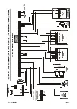
Page 17: ...ABLE PYRONIX PIR TAMPER ALARM SUPPLY PYRONIX PIR B B BT TF STB BA DECIBELL 2K2 4K7 ALARM SPARE N C 4K7 4K7 2K2 2K2 2K2 2K2 2K2 E SEE PAGE C 2K2 4K7 2K2 eg ACCESS ZONE HALL TAMPER ALARM SUPPLY EXTENSION SPEAKER OPTIONAL BATTERY K K KD KTKTR REST OF TELEPHONE SYSTEM KEYPAD TAMPER CONNECTIONS SHOULD BE WIRED TO A ZONE PROGRAMMED FOR TAMPER TELEPHONE NETWORK RKP 2K2 8 32 Line in ...

Page 18: ...TR REST OF TELEPHONE SYSTEM KEYPAD TAMPER CONNECTIONS SHOULD BE WIRED TO A ZONE PROGRAMMED FOR TAMPER TELEPHONE NETWORK RKP 2K2 E SEE PAGE C eg ACCESS ZONE HALL eg IMMEDIATE ZONE LIVING ROOM EXTENSION SPEAKER OPTIONAL OPTIONAL SIREN 12V MAGNETIC CONTACT eg EXIT ENTRY DOOR ALARM SPARE N C 8 32 TAMPER ALARM SUPPLY TAMPER ALARM SUPPLY Line in ...

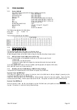
Page 19: ...g a tamper alarm 11 3 Setting Volume Control Extension speaker only This volume is controlled via the adjustable volume pot on the main processor board 1 Remove lid 2 Set volume pot to desired volume 3 Depress a number digit on the keypad to check desired volume has been reached 4 Replace cover In an alarm condition the volume control is overridden and the speakers will operate at full volume Note...

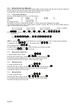
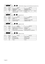
Page 20: ...en then then then then select SET A e a I I I t then then P F NOTE On pressing after selecting the attribute for zone 8 the programme for SET A will be stored automatically To programme SET B enter to programme SET C enter and to programme SET D enter Should you wish to view any zone status within a Set mode use the same procedure but do not scroll the keys Enter to exit 11 7 Setting the Alarm Bel...

Page 21: ... Enter followed by for following options 0 OFF programmable output 1 not used 1 PIR remote LED enable 2 PIR latch memory 3 Output switch 5 secs 4 Output switch reflecting setting and unsetting of panel 5 Follow zone Refer to 11 1121 for Zone allocation 6 Follow line fail 7 Follow kiss off 11 11 2 Programmable Output 2 Enter followed by for following options 0 OFF programmable output 2 not used 1 P...

Page 22: ... 24 hour test dial 2 Tamper Dial in No dial in 3 P A Wide handshake filters Standard handshake filters 4 Fire Silent P A zones Audible P A zones 11 11 5 System Option 3 Enter followed by to toggle RKP LEDs Key Function LED ON LED OFF 1 Alarm Engineer only NVM reset User NVM reset 2 Tamper Display open zones in day mode No display 3 P A Alarm in line fail No alarm in line fail 4 Fire Disable teleph...

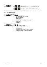
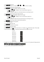
Page 23: ...digits will be stored automatically when the last digit is entered 11 11 10 Customer Account Code Issued by Central Monitoring Station Enter followed by the 4 digit code e g 4 digit 1 2 3 4 11 11 11 Downloading Access Code Enter followed by the 4 digit code 11 11 12 Zone Alarm reporting Codes Enter followed by 2 digits for each alarm zone To disable an event insert blanks in place of the two digit...

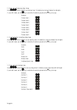
Page 24: ...ng Codes Enter Enter 2 digits for seven reporting codes To disable an event insert blanks for both digits To use HEX codes use the key to select the character required and the key to accept Example Set A Set B Set C Set C Duress Set Duress Unset Confirmed Alarm Code 11 11 15 User set reporting codes Enter Enter 2 digits for seven reporting codes To disable an event insert blanks for both digits To...

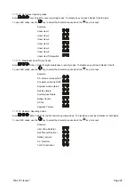
Page 25: ...nce priority codes To disable an event insert blanks for both To use HEX codes use the key to select the character required and the key to accept Example P A alarm entered at RKP Fire alarm entered at RKP Engineer mode entered Bell fuse failure Auxiliary fuse failure Battery trouble AC fail Keypress Tamper 11 11 18 Restoral Reporting Codes Enter Enter 2 digits for the five restoral reporting codes...

Page 26: ...cted the next group will be automatically selected Group 2 User Set Unset Codes Select from the list above where you require User Set Unset codes to be reported to Group 3 Maintenance Codes Select from the list above where you require Maintenance codes to be reported to Group 4 24hr Test call Select from the list above where you require 24hr Test Call codes to be reported to The dual tone sound in...

Page 27: ...e emitted every 5 seconds when the panel is in day mode Press a function key to stop the error tone The fault LED will remain on until the fault has been corrected To determine the fault go into the log by entering A symbol followed by 1 6 will be displayed 1 Bell Fuse Failure 2 Auxiliary Fuse Failure 3 Battery Missing 4 Low Battery Voltage 5 Mains Failure 6 Telephone Line Failure 8 Failure to com...

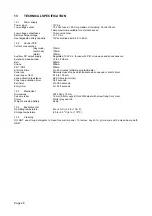
Page 28: ...robe 500mA PR1 PR2 250mA Alarm bell time 2 to 20 minutes software programmable Zone type Normally closed loops which activate when opened or short circuit Zone loop current 0 76 to 1 03mA Zone activation resistance 6 9K Ohms minimum Zone loop activation timer 0 35 seconds Exit timer 2 to 255 seconds Entry timer 2 to 255 seconds 13 3 Mechanical Dimensions 228 x 243 x 75 mm Case material 1 2mm 0 8mm...

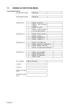
Page 29: ...m option 1 System option 2 System option 3 Spare Re Sets First telephone number Second telephone number Customer account code Downloading access code Zone alarming reporting codes Zone tamper reporting codes System set unset reporting codes User set reporting codes User unset reporting codes Maintenance and priority codes Restoral reporting codes Digicom codes Keyswitch set configuration Group rep...

Page 30: ...tion System Option 2 1 Default 24 hour test dial 2 Default no dial in 3 Default Standard filters 4 Default Audible P A System Option 3 1 Default User NVM reset 2 Default Open Zones not Displayed 3 Default No alarm in line fail 4 Default Telephone line monitoring off System Option 4 1 Default No bell squawk 2 Default Bell time mins 3 Default AC fail warning 4 Default Spare No of Re Sets Default Con...

Page 31: ...rm Zone 4 Alarm Zone 5 Alarm Zone 6 Alarm Zone 7 Alarm Zone 8 Alarm Tamper Alarm Reporting Codes Zone 1 Tamper Zone 1 Tamper Zone 1 Tamper Zone 1 Tamper Zone 1 Tamper Zone 1 Tamper Zone 1 Tamper Zone 1 Tamper System Set Unset Reporting Codes Set A Set B Set C Set D Duress Set Duress Unset Confirmed Alarm Code ...

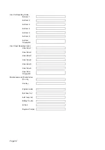
Page 32: ...Set User 6 Set User 7 Keyswitch User Unset Reporting Codes Unset User 1 Unset User 2 Unset User 3 Unset User 4 Unset User 5 Unset User 6 Unset User 7 Keyswitch Maintenance and Priority Codes P A Key Fire Key Engineer mode Bell Fuse Fail AUX Fuse Fail Battery Trouble AC Fail Keypress Tamper ...

Page 33: ...age 33 Restoral Reporting Codes User code Restoral Bell Timeout Restoral Battery Restoral A C Restoral Test Transmission Digicom Codes Keyswitch Set Configuration Group Allocation Group 1 Group 2 Group 3 24hr Test Call ...

Page 34: ...Page 34 ...

Page 35: ...Rins 181 Issue7 Page 35 ...

Reviews: