background image

PTC System Controls and Diagnostics                                                          


CP15 User Manual             CP15_UM_221017                                            Page 9 of 33 


6


Optional Items 

6.1  Power supplies and adaptors 

PSU1212-L.  +24 VDC to +/-12 VDC power supply, input for 2.1mm threaded jack, output 4 pin 
Lemo 0B.304. 


PSU1212-C.  +24 VDC to +/-12 VDC power supply, input for 2.1mm threaded jack, output 9 pin 
DSub female with pinout matching C400 connectors. 

PSU1212-N.  +24 VDC to +/-12 VDC power supply, input for 2.1mm threaded jack, output 9 
pin DSub female with pinout matching NIM standard pre-amp power connectors, 

PSU24-25-1.  Universal 24 VDC PSU, 25 W, 100-240 VAC 50-60 Hz input via IEC C8 
connector, S671K threaded jack output. 


Note:  If the CP15 is used with a C400, +/-12V power is provided by the C400. 

6.2  Cables and adaptors 

CAB-L00-10-L00  Lemo 00 coax cable assembly, 10’ (3 m).  For signal output. 

CAB-L00-30-L00  Lemo 00 coax cable assembly, 30’ (9 m).  For signal output. 


CAB-L304M-10-D9M  Power cable assembly, 10’ (3 m).  To power CP1x from PSU1212 or 
C400. 

CAB-L304M-30-D9M  Power cable assembly, 30’ (9 m).  To power CP1x from PSU-B12 or 
C400. 

ADAP-LEMO-BNC  Adaptor, Lemo 00 coax plug to BNC jack.  For signal output if using 
BNC-terminated cables. 

Other lengths available on request. 

Summary of Contents for CP15AF

Page 1: ...P15AL Pulse pre amplifiers User Manual Pyramid Technical Consultants Inc 135 Beaver Street Suite 102 Waltham MA 02452 USA US TEL 781 402 1700 FAX 781 402 1750 EMAIL SUPPORT PTCUSA COM Europe TEL 44 1273 492002 ...

Page 2: ...pplies and adaptors 9 6 2 Cables and adaptors 9 7 Intended Use and Key Features 10 7 1 Intended Use 10 7 2 Key Features 10 8 Specification 11 9 Installation 15 9 1 Mounting 15 9 2 Grounding and power supply 15 9 3 Connection to equipment 15 9 3 1 Typical setup 15 9 3 2 Setup with the C400 16 9 3 3 Effect of cable length 17 10 Comparison of CP15AF and CP15AL 18 11 Circuit overview 20 12 Setup and C...

Page 3: ... 4 Energy calibration 24 13 Connectors controls and indicators 26 13 1 Input end connectors controls and indicators 26 13 2 Output end connectors 26 13 2 1 Out 26 13 2 2 Power 12 V 26 13 3 Internal settings 27 14 Fault finding 28 15 Maintenance 30 16 Returns procedure 31 17 Support 31 18 Disposal 31 19 Declaration of Conformity 32 20 Revision History 33 ...

Page 4: ...y event from a NaI detector left and a LaCl3 right measured with CP15AF preamp 1 µsec per division 18 Figure 8 Single output for a 59 6 keV X ray event from a NaI detector left and a LaCl3 right measured with CP15AL preamp 1 µsec per division 19 Figure 9 CP15AF simplified block schematic 20 Figure 10 CP15AL simplified block schematic 20 Figure 11 CP15AF increasing gain setting showing saturation o...

Page 5: ...ges are present Appropriate precautions must be taken The unit should not be operated unless correctly assembled in its case Only Service Personnel as defined in EN61010 1 should attempt to work on the disassembled unit and then only under specific instruction from Pyramid Technical Consultants Inc or their authorized distributors The unit is designed to operate from 12 VDC power rails with a maxi...

Page 6: ... User Manual CP15_UM_221017 Page 6 of 33 Direct current Earth ground terminal Protective conductor terminal Frame or chassis terminal Equipotentiality Supply ON Supply OFF CAUTION RISK OF ELECTRIC SHOCK CAUTION RISK OF DANGER REFER TO MANUAL ...

Page 7: ...15AL Variable gain pulse pre amplifier optimized for use with lanthanum bromide or lanthanum chloride scintillation detectors FMB Oxford part CP 15L The following options for the CP15AL and CP15AF can be requested at time of order Jumper settings can be set in the field by trained service personnel I NI Overall inverting or non inverting default is inverting so that photomultiplier pulses give pos...

Page 8: ...ser Manual CP15_UM_221017 Page 8 of 33 5 Scope of Supply CP15 model as specified in your order USB memory stick containing Data sheet User manual Test results Optional items as specified in your order such as power supplies cables and adaptors ...

Page 9: ...IM standard pre amp power connectors PSU24 25 1 Universal 24 VDC PSU 25 W 100 240 VAC 50 60 Hz input via IEC C8 connector S671K threaded jack output Note If the CP15 is used with a C400 12V power is provided by the C400 6 2 Cables and adaptors CAB L00 10 L00 Lemo 00 coax cable assembly 10 3 m For signal output CAB L00 30 L00 Lemo 00 coax cable assembly 30 9 m For signal output CAB L304M 10 D9M Pow...

Page 10: ...tion event is converted to a single smooth output pulse well suited to discrimination or pulse height analysis The CP15AL also known as the CP 15L in FMB Oxford Ltd installations as gain and filtering suited to lanthanum bromide LaBr3 and lanthanum chloride LaCl3 scintillation detectors These detectors are considerably faster than sodium iodide detectors and more expensive and are preferred for hi...

Page 11: ...mpedance Maximum line length Able to drive at least 10 m of RG 58 RG 174 or RG 318 coaxial cable CP15AL Conversion gain 0 29 0 02 V per pC at maximum gain setting into 50 ohm load output pulse height for charge in input pulse 0 57 0 02 V per pC at maximum gain setting into high impedance load output pulse height to charge in input pulse Voltage gain 75 nominal 37 5 dB into 50 ohm load at maximum g...

Page 12: ...Case protection rating The case is designed to rating IP43 protected against solid objects greater than 1 mm in size protected against spraying water Weight 0 085 kg 3 0 oz Operating environment 5 to 35 C 15 to 25 C recommended to reduce drift and offset 80 humidity non condensing vibration 0 2 g all axes 1 to 100 Hz Shipping and storage environment 10 to 50C 80 humidity non condensing vibration 2...

Page 13: ...PTC System Controls and Diagnostics CP15 User Manual CP15_UM_221017 Page 13 of 33 Figure 1 CP15 case end panels Dimensions mm SIGNAL OUT LEMO EPL 00 250 NTN POWER LEMO EPG 0B 304 HLN ...

Page 14: ...trols and Diagnostics CP15 User Manual CP15_UM_221017 Page 14 of 33 Figure 2 CP15 underside showing mounting holes and side views Dimensions mm 78 5 6 7 24 0 64 0 30 0 18 5 4 0 27 0 35 0 4X TAPPED HOLE M2 5X0 45 x 5 ...

Page 15: ...led environment No forced air cooling is required but free convection should be allowed around the case 9 2 Grounding and power supply A secure connection should be made via the mounting screws to local ground potential If the unit is mounted on an insulating surface then one of the four mounting screws can be re assigned as a grounding connection 12 VDC and 12 VDC power should be provided from a ...

Page 16: ... overall inverting so that negative input charge gives a positive voltage the internal polarity jumper should be set to the default INV position 9 3 2 Setup with the C400 The C400 is a partner product to the CP15 It provides pulse discrimination and counting electronics for four independent channels each of which provides the bias pre amp power and signal processing for a detector system Detector ...

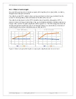
Page 17: ...possible although the CP15 is relatively tolerant of longer input cables when used with photomultiplier scintillation detectors Longer cable can alter the pulse amplitude and the signal level The following plots shows the measured amplitude and the rms noise level changed relative to a short cable as a function of coaxial length between the scintillation detector and the CP15 Figure 5 Effect of in...

Page 18: ...amp 1 µsec per division The role of the CP15 preamplifier is to collect this burst of pulses into a single clean pulse that is suitable for counting and pulse height analysis The CP15AF has a time constant large enough to collect all the output charge from a sodium iodide detector into a single output pulse It will perform the same task for a lanthanum halide detector but the speed advantage of th...

Page 19: ... Controls and Diagnostics CP15 User Manual CP15_UM_221017 Page 19 of 33 Figure 8 Single output for a 59 6 keV X ray event from a NaI detector left and a LaCl3 right measured with CP15AL preamp 1 µsec per division ...

Page 20: ...e on each stage and uses fast amplifiers throughout so that the much shorter pulses of lanthanum halide detectors are not broadened significantly permitting higher count rates A resistive divider gain control between the second and third gain stages allows the overall gain to be adjusted The offset potentiometer provides an adjustable voltage to compensate any DC offset A fourth inverting amplifie...

Page 21: ... 33 The CP15AF has a unity gain line driver matched to 50 ohms that allows large output pulses to be driven down long 50 ohm coaxial lines Incoming 12 V power is filtered and linear regulators produce the additional 5 V rails required A LED confirms that the 5 V supply is present ...

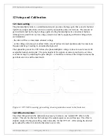
Page 22: ...taneously become more frequent and larger leading to unwanted background The adjustable gain of the CP15 allows the photomultiplier voltage to be set at a safe level with acceptable background signal The pulse height of the signals of interest can then be set into a convenient range by adjusting the gain trimpot A clockwise rotation of the trimpot increases the gain between zero and the maximum Fi...

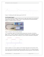
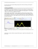
Page 23: ...tup for conversion gain calibration A 1 0 volt peak peak square wave with fast risetime delivered to this test box will deliver a charge of 1 0 0 05 pC to the CP15 at each transition of the square wave producing a series of positive and negative charges which in turn give a series of positive and negative going pulses Figure 14 Square wave into test capacitor and resulting charge pulses measured b...

Page 24: ...rgy analyser You will need to know at least one point to establish the calibration As an example you can calibrate a system comprising scintillation detector and the CP15AF using a suitable radiation source A convenient source is the Am 241 isotope which generates a 59 6 keV gamma ray which will create a peak at the high energy end of a pulse height spectrum If the application uses lower energy ra...

Page 25: ...PTC System Controls and Diagnostics CP15 User Manual CP15_UM_221017 Page 25 of 33 Figure 16 Determination of energy by linear scaling Counts 59 5 keV peak Vc Vu Pulse height Energy 59 5 Vu Vc ...

Page 26: ... when CP15 is powered 21 turn linear trimpot adjusting DC offset of output signal 21 turn linear trimpot adjusting gain from zero to maximum 13 2 Output end connectors 13 2 1 Out Lemo 00 coaxial connector for signal output Typical mating free connector Lemo FFA 00 250 13 2 2 Power 12 V Lemo 0B four pin female typical mating free connector FGG 0B 304 SIGNAL IN LEMO EPL 00 250 NTN POWER ON LED OFFSE...

Page 27: ... or degrade noise performance if correct handling precautions are not employed The following information is provided for reference To open the case remove two M2 5 hex cross head screws from each end of the case The top of the case can then be removed to reveal the circuit A 2 mm jumper near the output sets the relationship between the input signal polarity and the output signal polarity INV Outpu...

Page 28: ... Reduce threshold of pulse counting discriminator circuits if possible Wrong output pulse polarity scalers and MCAs generally require positive polarity shaped pulses Check output pulse polarity with oscilloscope Change CP15 internal polarity jumper setting No power to CP15 Check power LED check voltages Correct power supply Polarity jumper not in place Check that jumper is fitted to INV or NONINV ...

Page 29: ...r long transmission lines Output has DC offset Offset trim is incorrect Adjust trimpot to remove offset Adjust trimpot to remove offset Unexpected pulses Cosmic rays or other background seen by detector Turn off detector bias to see that pulses stop Move away from radiation background Move detector or add shielding if possible If cosmic ray rate is significant for the measurement add a coincidence...

Page 30: ...The CP15 does not require routine maintenance or calibration There is risk of contamination which may degrade performance if the case is opened in an uncontrolled environment If you need to access the unit to change jumper settings check first with your supplier or direct with Pyramid for guidance ...

Page 31: ...site at www ptcusa com Technical support is available by email from support ptcusa com Please provide the model number and serial number of your unit plus relevant details of your application 18 Disposal We hope that the CP15 gives you long and reliable service The CP15 is manufactured to be compliance with the European Union RoHS Directive 2002 95 EC and as such should not present any health haza...

Page 32: ...PTC System Controls and Diagnostics CP15 User Manual CP15_UM_221017 Page 32 of 33 19 Declaration of Conformity ...

Page 33: ... Revision History The release date of a Pyramid Technical Consultants Inc user manual can be determined from the document file name where it is encoded yymmdd For example M10_UM_080105 would be a M10 manual released on 5 January 2008 Version Changes CP15_UM_220929 First general release ...

Reviews: