PSI System Controls and Diagnostics
A500 User Manual
A500_UM_090115 Page 31 of 61
10
Functional overview
10.1 Cell controller
The core of the A500 is the cell controller board. Together with a dedicated processor for the
Ethernet port and an LCD display, this constitutes a high-performance real-time controller that
can service five fiber-optic loops with up to fifteen devices per loop. A large, fast FPGA handles
all communications, and a high speed floating-point digital signal processor handles data
manipulation. Only the services necessary for the application run on the A500, in contrast to the
typical situation on a PC, so that a fast, deterministic system can be implemented for real-time
data handling.
Ethernet
processor
Sharc DSP
FPGA
App code
Flash
SRAM
NVR
DC-DC
converters
24VDC
in
LCD
Communication
Fibre-optic loops
Cell controller board
Boot
Flash
I/O Port
I/O Port
Network
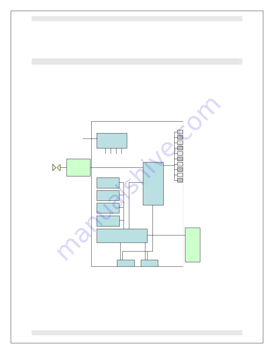
Figure 16. A500 schematic architecture
Bootloader code stored on a socketed flash memory device is executed on power-up. This
executes a power-on self-test (POST) of the whole device. The results are displayed on the
LCD. The A500 then waits for a message from the host which can either be a command to
download new application code, or to boot from a selection of one or more resident application


