1 Sec
90 Sec
30 Sec
Manual
Auto
Auto
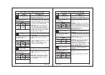
Sr.No.
Parameter
(LCD Message)
Description of parameters and functions.
Parameter setting
method.
09
LP SENSING DLY
HP / AFT RST
EXAMPLE:
If this parameter is set at 30
seconds, the system will ignore low
pressure alarm for 30 sec from
compressor on.In this manner, a false
alarm can be avoided due to low
pressure at compressor start up.
Use UP/DOWN keys to set desired
range.
Auto= it sets the HP- AFT faults for auto
reset.
Use UP/DOWN keys to set desired
range.
Manual= it sets the HP- AFT faults for
manual reset
To change the parameter,
press the set key.
To change the parameter,
press the set key.
14
15
Function:To set LP fault sensing delay.
Function: This parameter will set HP and
AFT fault to Auto or Manual reset.
Range
Range
Min
Min
Max
Max
Fact. Set
Fact. Set
LP FAULT RESET
16
Function: This parameter will set LP fault
to Auto or Manual reset.
press the set key.
To change the parameter,
Use UP/DOWN keys to set desired
range.
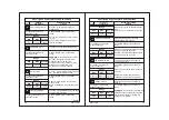
Sr.No.
Parameter
(LCD Message)
Description of parameters and functions.
Parameter setting
method.
10
Enable= This parameter enables Liquid
level sensing in the controller.
Disable= This parameter disables Liquid
level sensing in the controller.
Range
Min
Max
Fact. Set
Disable
Enable
Disable
PUMP RUN LOGIC
RELAY3 LOGIC
Use UP/DOWN keys to set desired
range.
Always On= it sets the pump to always
on mode.
With Comp =In this case pump will
switch ON and OFF with compressor.
Use UP/DOWN keys to set desired
range.
EXAMPLE:
If set to water sv
,
Relay3 will
switch on incase of liquid level is below
mid level.If set to Alarm, Relay3 will
switch on for all faults .
18
19
Function: This parameter configures
pump working logic.
Function: This parameter configures
Relay3.
Range
Range
Min
Min
Max
Max
Fact. Set
Fact. Set
To change the parameter,
press the set key.
To change the parameter,
press the set key.
Always On With Comp Always On
Alarm
Water SV
Alarm
press the set key.
To change the parameter,
LIQ LEVEL SENSOR
17
Function: This parameter enable /
disables liquid level sensing.
Use UP/DOWN keys to set desired
range.
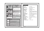
Use UP/DOWN keys to set desired
range.
0v- Trip the compressor or pump if fault
i/p is 0v
230V-Trip the compressor or pump if
fault i/p is 230Vac
press the set key.
To change the parameter,
Range
Min
Max
Fact. Set
0V
230 V
230V
Manual
Auto
Auto
Manual= it sets the LP fault for manual
reset
Auto= it sets the LP fault for auto reset.
Range
Min
Max
Fact. Set
FAULT SENS LOGIC
13
Function: To set tripping voltage of
digital inputs .
Contd.
NC-110A
NC-110A

