


Operating and maintenance instructions
EN
18
LI 2333.03
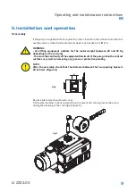
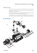
6.4 Exhaust filters replacement
Very dirty exhaust filters may cause a considerable pump temperature increase and in
extreme cases oil lubricant spontaneous ignition.
Maximum allowed pressure in the tank is 0,6 bar measured at the maximum capacity
(when the pump is working with the inlet open to atmospheric pressure).
If a pressure gauge has been fitted to the tank, check the exhaust filter blockage with
the pump warm.
To replace the filter, remove the cover (pos. B2) by unscrewing its screws (pos. B1).
Unscrew the screw (pos. B4), remove the washers (pos. B5-B6) and then the fixing
cartridge disk (pos. B7).
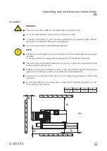
Replace all the exhaust filters (pos. B) and their O Rings (pos. B8). Reassemble the fixing
cartridge disk, the washers and tighten the screws.
Reassemble the discharge cover. If necessary, replace the gasket (pos. B3).
6.5 Spares necessary for the normal servicing
The recommended spares are shown in the list of the exploded drawing marked with
the letter “R” (see RDT). They are contained in the minor spare parts kit.
6.6 Pump overhaul
For this operation please request the proper instructions and direct any questions to
our Customer Service department. The overhaul consists of a complete disassembly,
cleaning of all components as well as replacement of parts that are subject to wear
(pump and motor bearings, vanes and gaskets).
6.7 How to order spare parts
When ordering spare parts, always state the pump model, serial number, year of produc-
tion, electric motor characteristics (manufacturer’s name, model, kW, V, Hz), position
reference on the spare parts list, description and quantity needed.
Different types of maintenance kits are available (ref. RDT attachment).