Nixie Tube Clock ‘LTC’
Issue 1 (1 November 2011)
www.pvelectronics.co.uk
- 13 -
4.4
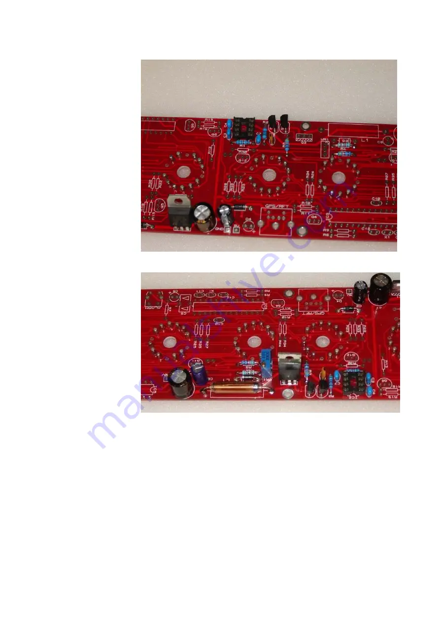
Q1 - BC639
Q2 - BC640
C3 - 330pF
C4 - 100nF
C6 - 33pF
C7 - 100nF
4.5
Q3 - IRFxxx
D3 - UF4004
L1 - Inductor
C5 - 470µF
C8 - 1µF
VR1 - 1K Pot
4.6
High Voltage Generator Test
- Refer to the warnings on page 4
- Power up the PCB, and using the GND and 170V test points, measure
the high voltage generated. It should be initially between 150 and 190V. -
- Using the VR1 brass screw, slowly adjust the screw until the voltage is
between 170 and 175V. Disconnect the power supply.


