background image

STEP 9 –


3PDT

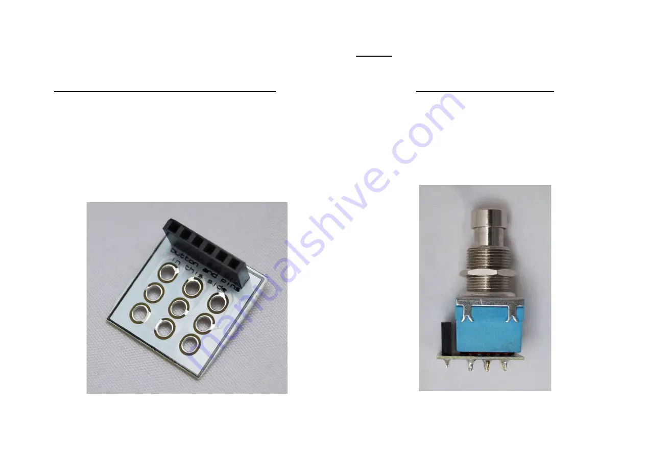
A – Solder the pin to the adapter 

Pay attention, the pins and the 3PDT 

must be soldered to the same side of 

the PCB adapter (the one labeled 

“buttons and 3PDT on this side”).  

B – Solder the 3PDT 

Now solder the 3PDT to the PCB and 

remove all the nuts but one, that should 

be set at a middle height: 


Summary of Contents for DR. Q ENVELOPE FILTER

Page 1: ...DR Q ENVELOPE FILTER ...

Page 2: ...ere we have put together a few links that detail some of the aspects explained in this manual and that we think you can find helpful Kit PuzzleKit general manual Reading resistor and capacitor values Also in our blog you can find multiple articles regarding tips for soldering more in depth posts about resistors and capacitors Check it out ...

Page 3: ...1 R6 220 1 R7 10k 3 R8 R9 R10 470k 1 R13 100 Capacitors 9 2 C1 C3 10n 1 C2 22u electrolytic 1 C4 100n 2 C5 C6 4 7n 1 C7 1n 2 C8 C9 47u electrolytic Transistors 1 1 Q1 2N3904 ICs 1 1 U1 TL072 Potentiometers 1 ATTACK 1kB lin 1 RANGE 20kB lin 1 SENS 100kB lin Other 2 2 L1 L2 LED 5mm red 1 DP 1N4007 1 RON 1k ...

Page 4: ...DR Q ENVELOPE FILTER Part Placement ...

Page 5: ...DR Q ENVELOPE FILTER STEP BY STEP GUIDE ...

Page 6: ...esistors and diodes If you have troubles reading the values check out our Reading Part Values tutorial Resistors 14 5 R1 R2 R11 R12 R15 47k 1 R3 3 3M 1 R4 51 1 R5 22k 1 R6 220 1 R7 10k 3 R8 R9 R10 470k 1 R13 100 Other 2 1 DP 1N4007 1 RON 1k ...

Page 7: ... IC sockets Pin header First of all place the IC sockets without the ICs Pay attention to the orientation The small notch in the socket should be oriented as indicated in the PCB Then connect the 6 pin header ...

Page 8: ...roubles reading the values check out our Reading Part Values tutorial Pay attention to the orientation as well as to the polarity for electrolytic capacitors Capacitors 9 2 C1 C3 10n 1 C2 22u electrolytic 1 C4 100n 2 C5 C6 4 7n 1 C7 1n 2 C8 C9 47u electrolytic Transistors 1 1 Q1 2N3904 ...

Page 9: ... LED and Battery Clip Solder two wires to the LED connection red to the sign Then solder then to the LED the red wire is connected to the longer pin Solder the battery clip connecting the red wire to the sign ...

Page 10: ...STEP 5 DC Power Jack wires Solder three wires about 5cm each to the DC connection as shown don t solder anything to the other end yet ...

Page 11: ...STEP 6 Audio Jacks Now solder the audio jacks to the board DC battery and led wires are not present to make it clearer ...

Page 12: ...eces of wire for each potentiometer you have to solder i e 9 pieces for 3 potentiometers Then solder them to each lug The first lug is the one in the left in top view the black wire in the picture Here we ve cut them short 1cm but you can use the length you need ...

Page 13: ...Then solder them to the board like in the picture in the left and then place the board inside the enclosure ...

Page 14: ...STEP 8 DC Power Jack First of all insert the DC jack in the enclosure and tighten the nut Then solder the three wires from the DC connector in the board to the DC jack as follows ...

Page 15: ...attention the pins and the 3PDT must be soldered to the same side of the PCB adapter the one labeled buttons and 3PDT on this side B Solder the 3PDT Now solder the 3PDT to the PCB and remove all the nuts but one that should be set at a middle height ...

Page 16: ...e 3PDT directly to the board optional If you prefer to solder the 3PDT directly to the board you can wire it as shown in the schematic We recommend to use the provided 3PDT PCB adapter to make the soldering easier ...

Page 17: ...STEP 10 Connect the 3PDT STEP 11 Your pedal is finished By now you should have a fully functional effect pedal we hope you enjoy it ...

Reviews: