User Manual
PT-SP-HD116DA
11
5.
DIP Switch Operation
The 4-pin DIP switch on the front panel of the unit is used for EDID management and
HDCP management. It represents “
0
” when in the lower (
OFF
) position, and it
represents “
1
” while putting the switch in the upper (
ON
) position.
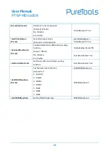
Switch 1~3 are used for EDID setting. The switch status and its corresponding setting
are shown at the below chart.
Switch Status
(PIN 1~3)
EDID Value
1
2
3
0
0
0
Obtains EDID from the first detected display starting at HDMI
OUT1>OUT2>.........>OUT16.
0
0
1
1920x1080@60Hz 8bit Stereo
0
1
0
1920x1080@60Hz 8bit High Definition Audio
0
1
1
3840x2160@30Hz 8bit Stereo Audio
1
0
0
3840x2160@30Hz Deep Color High Definition Audio
1
0
1
3840x2160@60Hz Deep Color Stereo
1
1
0
3840x2160@60Hz Deep Color HDR LPCM 6CH
Switch 4 is used for HDCP setting. The switch status and its corresponding setting are
shown at the below chart.
Switch 4 Status
HDCP
OFF (0)
Automatically follows the HDCP version of display device.
When display device has no HDCP, if source device have no HDCP content, the
video output has no HDCP content; if source device has HDCP content, there are
no video output.
ON (1)
Automatically follows the HDCP version of source device.
Note:
The factory default switch status is “0000”, and it needs to be set to “1111” when
enable RS232 control to set EDID and HDCP.
Summary of Contents for PT-SP-HD116DA
Page 23: ...User Manual PT SP HD116DA ...


