background image

User Manual

PT-PMS-42

39

9. Firmware Upgrade

Please follow the steps as below to upgrade firmware by the

FIRMWARE

port on the rear

panel:

1) Prepare the latest upgrade file (.bin) and rename it as “USERAPP.bin” on PC.

2) Power off the switcher, and connect the

FIRMWARE

port of switcher to the PC with USB

cable.

3) Power on the switcher, and then the PC will automatically detect a U-disk named of

“BOOTDISK”.

4) Double-click the U-disk, a file named of “READY.TXT” would be showed.

5) Directly copy the latest upgrade file (.bin) to the “BOOTDISK” U-disk.

6) Reopen the U-disk to check the filename “READY.TXT” whether automatically becomes

“SUCCESS.TXT”, if yes, the firmware was updated successfully, otherwise, the firmware
updating is fail, the name of upgrade file (.bin) should be confirm again, and then follow
the above steps to update again.

7) Remove the USB cable after firmware upgrade.

8) After firmware upgrade, the switcher should be restored to factory default by sending

command.

Summary of Contents for PT-PMS-42

Page 1: ...User Manual PT PMS 42 User Manual Seamless Presentation Matrix 4x2 3 HDMI DP HDMI HDBT matrix outputs Model PT PMS 42 Designed in Germany 2020 PureLink GmbH All rights reserved V1 2 ...

Page 2: ...ied or reproduced without the prior written consent FCC Statement This equipment generates uses and can radiate radio frequency energy and if not installed and used in accordance with the instructions may cause harmful interference to radio communications It has been tested and found to comply with the limits for a Class B digital device pursuant to part 15 of the FCC Rules These limits are design...

Page 3: ...907 2006 EU und 2011 65 EU EMC LVD Electro Magnetic Compatibility LowVoltage Directive PureLink GmbH hereby declares that this product PureTools PT PMS 42 complies with Directives 2014 30 EU and 2014 35 EU The full text of the EU Declaration ofConformity is available at the following Internet address http www purelink de ce 4251364718216_CE pdf ...

Page 4: ...ll this product near water Do not put any heavy items on the extension cable in case of protrusion Do not remove the housing of the device as opening or removing the housing may expose you to dangerous voltage or other hazards Install the device in a place with sufficient ventilation to avoid damage caused by overheat Keep the module away from liquids Spillage into the housing may result in fire e...

Page 5: ...0 5 3 SoundVolume Control 11 6 IR Remote Control 11 7 GUI Control 12 7 1Video Switching 13 7 2 Audio Control 14 7 3 EDID Management 16 7 4 CEC Control 17 7 5Tags Setting 19 7 6 RS232 Control 20 7 7 Network Setting 22 7 8 Password Setting 23 7 9 GUI Update 24 8 RS232 Control 25 8 1 RS232 Control Software 25 8 2 RS232 Communication Command 30 8 2 1 Device Control 30 8 2 2 Source Switching 31 8 2 3 A...

Page 6: ...DBT output stream which may be muted the audio is simultaneously de embedded to an analog audio output The switcher features multiple methods of control When set toAuto the switcher will automatically switch to the newest source device added to the switcher when the active source is removed the switcher will switch to the first detected input The switcher can be manually controlled by front panel ...

Page 7: ...her 2x Mounting Ears with 4 Screws 4x Plastic Cushions 1x IR Receiver 1x IR Emitter 1x IR Remote 2x 3 pinTerminal Blocks 1x 5 pinTerminal Block 1x Power Adaptor 24V DC 2 71A HDBaseT Receiver 1x PT HDBT 200 RX HDBaseT Receiver 2x Mounting Ears with 2 Screws 4x Plastic Cushions 1x 3 pinTerminal Block 1x User Manual Note Please contact your distributor immediately if any damage or defect in the compo...

Page 8: ...tor 1 Type A female HDMI 1 RJ45 HDMI Output Resolution Up to 4Kx2K 60Hz 4 4 4 8bit HDBT Output Resolution Up to 4Kx2K 60Hz 4 2 0 8bit HDMIVersion 2 0 HDCPVersion 2 2 MHLVersion 2 2 DPVersion 1 2 HDR Supported CEC Supported HPD Supported Audio Input Input 1 MIC 1 LINE InputConnector 2 3 pin terminal blocks HDMI InputAudio Format PCM 7 1 audio Dolby Atmos Dolby TrueHD Dolby Digital Plus DTS X and DT...

Page 9: ...92KHz AC3 DTS Max Output Level 0 1 80 dB 20Hz 20KHz bandwidth 1KHz sine at 0 dBFS level or max level THD N 0 1 80 dB 20Hz 20KHz bandwidth 1KHz sine at 0 dBFS level or max level SNR 80dB Crosstalk Isolation 75dB 10KHz sine at 0dBFS level or max level before clipping L R Level Deviation 0 5dB 1KHz sine at 0dBFS level or max level before clipping Frequency Response Deviation 0 5 dB 20Hz 20KHz Output ...

Page 10: ... Video Input Connector 1 RJ45 Video Output 1 HDMI Video Output Connector 1 Type A female HDMI Control Port 1 IR IN 1 IR OUT 1 RS232 Control Connector 2 3 5mm mini jacks 1 3 pin terminal block General Transmission Distance 1080P 70m 4Kx2K 40m Resolution Up to 4K 2K 60Hz 4 4 4 8bit Bandwidth 18Gbps HDMI Version 2 0 HDCP Version 2 2 Power Consumption 14W max Operation Temperature 10 55 Storage Temper...

Page 11: ... the 1 4 button to select input source respectively and its corresponding LED lights up green Press the AUTO button to enable automatic switching mode and its LED lights up green Press again to exit 4 OUTPUT Press the button to select output channel 5 Volume Knob and LED Press the knob in to toggle among MIC HDMI OUT and HDBT OUT audio control and the corresponding LED will light up green Rotate t...

Page 12: ...ock to connect wireless microphone or line audio input source MIC 3 pin terminal block to connect condenser or dynamic microphone input 3 OUTPUTS 1 HDMI Type A female HDMI output port to connect video display 2 HDBT Supports PoC RJ45 connector to connect the HDBaseT receiver by CATx cable 4 CONTROL IR IN 3 5mm mini jack to connect an IR receiver for IR pass through control IR OUT 3 5mm mini jack t...

Page 13: ... control mode UPDATE A UpdateValens IC program connect a PC to the RS232 port and then double click the update file bat UPDATE B Update compression IC program the upgrade method is the same as the above UPDATEA 2 Power LED The LED lights up red when the device is powered on 3 HDMI OUT Type A female HDMI output port to connect video display 4 RS232 3 pin terminal block for RS232 pass through contro...

Page 14: ...power cords should be insulated and safe All devices should be connected before power on 4 2 System Diagram 3 HDMI 2 HDMI 1 HDMI MHL 4 DP 1 HDMI 2 HDBT L R AUDIO 48V LINE L R OFF MIC IR EYE IR IN IR OUT FIRMWARE RS232 Tx Rx INPUTS OUTPUTS AUDIO INPUTS CONTROL ON DC 24V Laptop Remote Control System Laptop TV DVD IR Receiver Router Game Console MacBook Microphone Audio Player Receiver Speaker Remote...

Page 15: ...Auto mode LED will light up When in Auto mode the switcher will switch according to the following rules New input Upon detecting a new input the switcher will automatically select the new input Reboot Once power is restored to the switcher it will automatically reconnect the input before powered off Source removed When an active source is removed the switcher will switch to the first available act...

Page 16: ...mute 6 IR Remote Control Connect the IR EYE port to an IR receiver the switcher can be controlled by the below IR remote 3 HDMI AUTO 4 DP BLACK 3 HDMI AUTO 4 DP BLACK 2 3 6 5 4 7 8 9 10 1 1 Enter or exit standby mode 2 Select input source for HDMI output 3 Enable disable automatic switching mode for HDMI output 4 HDMI output black screen 5 Select input source for HDBT output 6 Enable disable autom...

Page 17: ...rol The switcher also be controlled viaTCP IP The default IP settings are IP Address 192 168 0 178 Subnet Mask 255 255 250 0 Type 192 168 0 178 in the internet browser it will enter the below log in webpage Username admin Password admin ...

Page 18: ...ser name and password and then click Login to enter the section for video switching HDMI OUTPUT Switch the selected input source to HDMI output HDBT OUTPUT Switch the selected input source to HDBT output Preset Save the current routing status to preset 1 4 ...

Page 19: ...User Manual PT PMS 42 14 7 2 Audio Control 1 Input audio control LineVolume Mute Volume Up orVolume Down MICVolume Mute Volume Up orVolume Down Gain Level Adjust the gain level for input audio source ...

Page 20: ...elect LINE or MIC or both of them to mix with the HDMI de embedded audio or HDBT de embedded audio If select MIC or LINE for the HDBTOutput the Audio Output will automatically select the same audio Volume Volume control bar for output audio Mute Volume Up orVolume Down Bypass Enable or disable Bypass mode The default is OFF the audio output format is PCM When in Bypass mode the output audio format...

Page 21: ...User Manual PT PMS 42 16 7 3 EDID Management Select the compatible built in EDID for 1 HDMI MHL 2 HDMI 3 HDMI or 4 DP input source Upload user defined EDID ...

Page 22: ...and display are supports CEC they can be controlled by the below control buttons to replace IR remote 1 1 HDMI Output Channel Source Control Select the input source which needs to be control and then press source control button Display Control Press control button ...

Page 23: ...User Manual PT PMS 42 18 2 2 HDBT Output Channel Source Control Select the input source which needs to be control and then press source control button Display Control Press control button ...

Page 24: ...User Manual PT PMS 42 19 7 5 Tags Setting INPUTS Modify the label of input sources Preset Modify the label of presets ...

Page 25: ...able RS232 pass through mode The RS232 port of the switcher can be used to transfer commands to control other third party devices Local Control Disable RS232 pass through mode The RS232 port of the switcher is used to connect control device such as PC to control the switcher ...

Page 26: ... of the PT PMS 42 switcher HDBT Send RS232 commands to control the far end third party such as projector which is connected to the RS232 port of HDBaseT receiver Select HEX or ASCII format Baud Rate Supports 2400 4800 9600 19200 38400 57600 or 115200 Command Ending NULL CR LF or CR LF can be chosen Command Type command in this box to control the third party device ...

Page 27: ...User Manual PT PMS 42 22 7 7 Network Setting Static IP or Dynamic Host Configuration Protocol DHCP Modify the static IP Address Subnet Mask andGateway ...

Page 28: ...User Manual PT PMS 42 23 7 8 Password Setting Modify the login password Lock or unlock the front panel buttons ...

Page 29: ...ername and password the same as the GUI log in setting modified password will be available only after rebooting to login the configuration interface After that click Administration in the source menu to get to Upload Firmware as shown below Select the update file and click Apply button it will start upgrading then ...

Page 30: ...ample Installation Please download the latest SoftwareVersion from the link below https docklight de download Docklight zip Then follow the installation wizard for installation on Windows 7 and 10 After the installation Docklight can be run for the first time and should look like the below screen shot Registration is not necessary unless you wish to save settings on exit so unless you wish to regi...

Page 31: ...p window can also be closed with Continue An empty project is enough to send and receive commands easily The default setting is always Start with a blank project blank script Click Continue to close this window Click OK to close this window ...

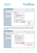
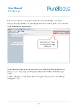
Page 32: ...e click on COM1 in the corresponding setup window In the following window select the drop down menu labeled Send Receive on Comm Channel select the appropriate COM port and then click on OK at the bottom right corner All other settings can be left at default for most applications but refer to device RS232 settings to be sure Double click on COM1 to change to the right COM port ...

Page 33: ...licking on Play 1 Then the keyboard function must be activated so that commands can be written in the communication window 2 Finally enter the command for example 50701 This is then confirmed by pressing Enter to send Any response from the connected device will appear in red 3 Select the right COM port ...

Page 34: ...User Manual PT PMS 42 29 Click Play to open the communication Enable the keyboard type in function Command sending area Monitoring area indicates if the command sent works 1 2 3 ...

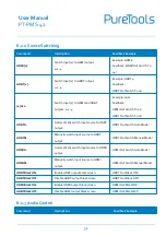
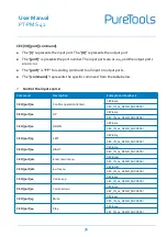
Page 35: ... 192 168 0 178 SetGuiIP xxx xxx xxx xxx Set GUI IP to xxx xxx xxx xxx SetNoSigTime xxx Set the automatic power off time to xxx Set the xxx as 0 to disable this function No Signal Auto StandBy Time Is 0S Rs232HDBTBypassON Enable RS232 pass through mode Note This function can only be disabled by Telnet or GUI Rs232 HDBT Bypass ON Rs232HDBTBypassOFF Disable RS232 pass through mode Note The command mu...

Page 36: ...ch input source to HDBT output HDBT Out Switch Auto Mode HDBTM Manually switch input source to HDBT output HDBT Out Switch Manual Mode HDMIA Automatically switch input source to HDMI output HDMI Out Switch Auto Mode HDMIM Manually switch input source to HDMI output HDMI Out Switch Manual Mode HDBTBlackON Enable HDBT output black screen HDBT Out Black ON HDBTBlackOFF Disable HDBT output black scree...

Page 37: ...olume to xx Volume of MIC 80 MicVolume Increase MIC volume Volume of MIC 81 MicVolume Decrease MIC volume Volume of MIC 79 MicMute Mute MIC audio Volume of MIC Mute MicUnMute Unmute MIC audio Volume of MIC UnMute LineVolume xx Set the line volume to xx Volume of Line 50 LineVolume Increase line volume Volume of Line 51 LineVolume Decrease line volume Volume of Line 49 LineMute Mute line audio Volu...

Page 38: ...HDBT Out 61 HDBTOutVolume Decrease HDBT output volume Volume of HDBT Out 59 HDBTOutVolumeMute Mute HDBT output audio Volume of HDBT Out Mute HDBTOutVolumeUnMute Unmute HDBT output audio Volume of HDBT Out Unmute 8 2 4 Preset Setting Command Description Feedback Example PresetSave x Store the current switching status to preset x x 1 4 Example PresetSave1 Feedback Preset1 Save Success PresetRecall x...

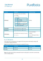
Page 39: ...eedback Input 2 EDID From 02 Internal EDID Explanation The input 3 is invoking the EDID 2 Example EDIDSTA03 Feedback Input 3 EDID From User Define EDID Explanation The input 3 is invoking the user defined EDID EDIDUpgrade x Upgrade the EDID data of the input port x x 0 All inputs x 1 4 1 4 input x U User defined EDID When the command applied system prompts to upload the EDID file bin Operation wil...

Page 40: ...HDBT output EDIDM x B y Set the EDID data of output x to input y x 1 2 y 1 4 Example EDIDM1B1 Feedback Input 1 EDID Upgrade OK By 01 EXT EDID 8 2 6 CEC Control If the input sources and displays are supports CEC they can be controlled by sending CEC commands to replace IR remote Step 1 According to the below command to enable CEC control Command Description Feedback Example CEC_ON Enable CEC CEC ON...

Page 41: ...ck CECI port 00 Confirm operation Enter CECI0100 CEC_IN_01_SEND_SUCCESS CECI port 01 UP CECI0101 CEC_IN_01_SEND_SUCCESS CECI port 02 DOWN CECI0102 CEC_IN_01_SEND_SUCCESS CECI port 03 LEFT CECI0103 CEC_IN_01_SEND_SUCCESS CECI port 04 RIGHT CECI0104 CEC_IN_01_SEND_SUCCESS CECI port 0A Enter main menu CECI010A CEC_IN_01_SEND_SUCCESS CECI port 0D Exit menu CECI010D CEC_IN_01_SEND_SUCCESS CECI port 41 ...

Page 42: ...SEND_SUCCESS CECI port 4C Backward CECI014C CEC_IN_01_SEND_SUCCESS CECI port 6C Power off CECI016C CEC_IN_01_SEND_SUCCESS CECI port 6D Power on CECI016D CEC_IN_01_SEND_SUCCESS Control the output display Command Description Example and Feedback CECO port 41 Volume up CECO0141 CEC_OUT_01_SEND_SUCCESS CECO port 42 Volume down CECO0142 CEC_OUT_01_SEND_SUCCESS CECO port 43 Mute CECO0143 CEC_OUT_01_SEND...

Page 43: ...y device X 1 2400 X 2 4800 X 3 9600 X 4 19200 X 5 38400 X 6 57600 X 7 115200 3 2 123456 Send the command 123456 to the third party device The baud rate is 9600 CMDON X xxx Power on the third party device CMDON 3 455665 CMDOFF X xxx Power off the third party device CMDOFF 3 455666 Note When sending HEX command in this box the X Y and the end mark must be converted to hexadecimal characters For exam...

Page 44: ...k named of BOOTDISK 4 Double click the U disk a file named of READY TXT would be showed 5 Directly copy the latest upgrade file bin to the BOOTDISK U disk 6 Reopen the U disk to check the filename READY TXT whether automatically becomes SUCCESS TXT if yes the firmware was updated successfully otherwise the firmware updating is fail the name of upgrade file bin should be confirm again and then foll...

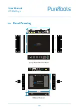
Page 45: ...WARE RS232 Tx Rx INPUTS OUTPUTS AUDIO INPUTS CONTROL ON DC 24V 220 0mm 44 0mm 172 5mm VOLUME IR 1 HDMI MHL 1 HDMI 4 DP AUTO 3 HDMI 2 HDMI INPUT OUTPUT 2 HDBT MIC HDBT OUT HDMI OUT MUTE 3s 4x2 Presentation Matrix Multiformat Matrix 4K 60Hz 4 4 4 HDMI HDBaseT Out PT PMS 42 4x2 4K Presentation Switcher 115 0 mm 84 0 mm 16 0 mm HDBaseT Receiver ...

Page 46: ... the power cord connection is good EDID management does not work normally The HDMI cable is broken at the output end Change for another HDMI cable which is in good working condition Static becomes stronger when connecting the video connectors Bad grounding Check the grounding and make sure it is connected well Cannot control the device by control device e g a PC through RS232 port Wrong RS232 comm...

Page 47: ...r a fee Warranty expiration Factory applied serial number has been altered or removed from the product Damage deterioration or malfunction caused by Normal wear and tear Use of supplies or parts not meeting our specifications No certificate or invoice as the proof of warranty The product model shown on the warranty card does not match with the model of the product for repairing or had been altered...

Page 48: ... Technical Support Phone 49 5971 800299 0 Fax 49 5971 800299 99 Technical Support Hours 8 30 AM to 5 00 PM Monday thru Thursday 8 30 AM to 4 00 PM Friday Write to PureLink GmbH Von Liebig Straße 10 D 48432 Rheine www purelink de info purelink de ...

Reviews: