Pulsar PG5250B Operator'S Manual Download Page 16

OPERATION

16

Do not connect 3-phase loads to generator.

CAUTION!

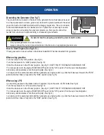
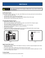
Extension Cord Selection

Refer to the below table to ensure the extension cord used has the capacity to carry the required load.  If the size of the 

cable is inadequate it can cause a voltage drop, which can damage the electrical device and cord.

Current 

(Amps)

Load (Watts)

Maximum Cord Length

230V

#8 Wire

#10 Wire

#12 Wire

#14 Wire

#16 Wire

2.5

600

X

1000 ft.

600 ft.

375 ft.

250 ft.

5

1200

X

500 ft.

300 ft.

200 ft.

125 ft.

7.5

1800

X

350 ft.

200 ft.

125 ft.

100 ft.

10

2400

X

250 ft.

150 ft.

100 ft.

50 ft.

15

3800

X

150 ft.

100 ft.

65 ft.

X

20

4800

175 ft.

125 ft.

75 ft.

X

X

25

6000

150 ft.

100 ft.

X

X

X

30

7200

125 ft.

65 ft.

X

X

X

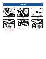
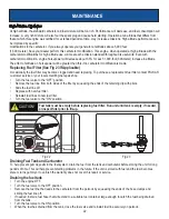
Moving the Generator

Disconnect any electronic devices from generator then turn generator off.

Turn fuel valve to the “OFF” position.

Tilt generator until it balances on wheels. Roll machine to desired location.

If the generator must be carried, fold handle to the down position.  Never lift or carry generator by its handle.

CAUTION!

This product is heavy and requires several people to lift.  Lift and lower with your legs by bending

at the knees, not your back, to avoid injury.

Don’t Overload Generator

Make sure you can supply enough rated watts and surge watts for all electronic devices connected to the generator. Rated 

watts refer to the power a generator must supply to keep a device running. Surge watts refer to the power a generator 

must supply to start an electronic device. This power surge for starting a device usually lasts between 2-3 seconds but this 

additional output must be taken into account when selecting the electronic devices you plan to attach to the generator. To 

prevent overloading the generator take the following steps:

120 / 240 Volt AC, 30 Amp locking receptacle

This receptacle has a 30 Amp push-to reset circuit breaker to protect against overload.

This receptacle is rated to operate 120 Volt, AC, single phase, 60Hz loads requiring up to 3600 watts (3.6 kW) at 30

Amps. It is also rated to operate 240 Volt AC, single phase, 60Hz loads requiring up to 7,200 watts (7.2 kW).

Use a NEMA L14-30 plug with this receptacle.

Use a 4-wire cord rated for 240 Volts AC, 30 Amps to the plug. You can use the same 4-wire cord to operate a 120

Volt load.

12 Volt 8.3 Amp Output is for charging batteries only!

WARNING!

Summary of Contents for PG5250B

Page 1: ...www pulsar products com OPERATOR S MANUAL Warning The Engine Exhaust from this product contains chemicals known to the State of California to cause cancer birth defects or other reproductive harm Mode...

Page 2: ...gine oil 11 Adding Fuel 12 Connecting Generator to an Electrical System 12 Operation 13 Grounding the Generator 13 How to Start Engine 13 How to Stop Engine 14 Receptacles and Extension Cords 15 Don t...

Page 3: ...Specifications To order parts receive warranty assistance or other services inquiries you can contact us at www pulsar products com The emissions control system for this generator is compliant with al...

Page 4: ...serious injury avoid attempting to lift the generator alone WARNING Safety Instructions Using a generator indoors WILL KILL YOU IN MINUTES Carbon monoxide gas is a poisonous odorless gas that can cau...

Page 5: ...If unit has been running then the fuel cap is under pressure remove slowly To keep fuel from spilling secure unit so it cannot tip while operating or transporting When transporting unit disconnect the...

Page 6: ...nerator on a level surface Always connect the nut and ground terminal on the frame to an appropriate ground source WARNING Generator must be properly grounded to prevent electrocution Never handle the...

Page 7: ...eter C Circuit Protectors D Main Circuit Breaker E Voltage Selector F Two 120 V Receptacles G 30 Amp RV Receptacle H 120 240 Volt AC 30 Amp twist lock receptacle NEMA L14 30 I Ground Terminal J Fuel S...

Page 8: ...nt L Fuel Gauge M Generator Frame N Choke Lever O Air Filter P Pull Start Q Handle R Support Foot S Fuel Cap T Gas Tank U Fuel Valve V Oil Fill Dipstick W Propane Inlet X No Flat Wheels FEATURES S T U...

Page 9: ...ve generator on box to install wheel assembly Description Qty Handles Screw Nut 1 4 4 Wheels 2 Hair pin 2 Axles 2 Packing List Check all loose parts to the following list Contact your dealer if any lo...

Page 10: ...using M8 screws 2 and nuts Installing Support Leg See fig 2 Parts needed 2 wheels 2 axles 2 hair pins and 2 washers Raise or tilt generator so you can slide the wheel axle pin into the wheel the washe...

Page 11: ...dipstick hold and carefully add 4 Cycle engine oil SAE10W 30 to empty reservoir until oil reaches the outer edge of the oil fill hole crankcase dipstick hole Be sure to replace dipstick before attempt...

Page 12: ...y or death to electric utility workers WARNING This generator produces a very high voltage which could result in burn or electrocution causing serious injury or death Connecting Generator to an Electr...

Page 13: ...ion See fig 9 Turn the fuel selector to GAS position See fig 10 Slide the choke lever to the Choke position See fig 11 SKIP THIS IF THE ENGINE IS WARM OR HOT For manual start turn the engine START ON...

Page 14: ...OPERATION 14 Fig 9 Fig 13 CHOKE RUN CHOKE LEVER CHOKE RUN CHOKE LEVER WAIT 5sec Fig 11 SKIP THIS IF THE ENGINE IS WARM OR HOT Fig 12 Recoil Start Fig 8 Fig 10 GAS PROPANE START...

Page 15: ...rd This generator is equipped with the following receptacles How to Stop Engine See fig 14 17 All loads MUST be disconnected from the generator Never start or stop the engine with electrical devices p...

Page 16: ...ple to lift Lift and lower with your legs by bending at the knees not your back to avoid injury Don t Overload Generator Make sure you can supply enough rated watts and surge watts for all electronic...

Page 17: ...ic Blanket 400 400 Space Heater 1800 1800 Kitchen Blender 300 900 Toaster 2 slice 1000 1600 Coffee Maker 1500 1500 Electric Range 1 element 1500 1500 Dishwasher 1500 3000 Electric Oven 3410 3410 Elect...

Page 18: ...lest output last to help prevent overloading the generator Allow generator output to stabilize engine and attached devices run evenly before plugging in the next load Fig 18 Cold Weather Operation Und...

Page 19: ...sure the air filter is clean Remove any debris that has collected on the generator and around the muffler and controls Use a vacuum cleaner to pick up loose debris If dirt is caked on use a soft bris...

Page 20: ...res determine the proper oil viscosity for the engine Use the chart to select the best viscosity for the outdoor temperature range expected Carefully add SAE 10W 30 to empty reservoir until the oil re...

Page 21: ...Equivalent To clean remove the air filter cover Carefully pull the air filter out by lifting up along the edges Remove dirt from filter by tapping on it or having it blown out Replace with new filter...

Page 22: ...close the fuel valve and reinstall fuel line securely on petcock Remove the fuel line that leads to the carburetor from the petcock by squeezing the ends of the hose clamps and sliding the fuel line...

Page 23: ...owly pull the recoil Starter until you feel the engine build compression When you feel resistance Leave the Engine in this state as this will prevent any corrosion on the cylinder walls if stored for...

Page 24: ...er in fuel 8 Fuel valve is in OFF position 9 Over choking 10 Low oil level 11 Rich fuel mixture 12 Intake valve stuck open or closed 13 Loss of engine compression 14 Dead battery 15 Engine has flooded...

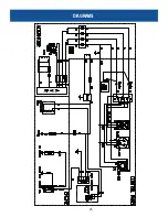
Page 25: ...DIAGRAMS 25...

Page 26: ...or components parts and labor Year 2 Limited coverage on generator engine components parts only Personal use means personal residential household use or recreational use by the retail consumer Commerc...

Page 27: ...in the United States Canada or Mexico Refurbished used demonstration or floor models are not covered by this warranty Products purchased from on line auction websites such as ebay are not covered und...

Reviews: