


10
CONTROL PANEL FUNCTIONS
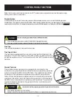
Fuel Cap
Turn counterclockwise to remove the fuel cap.
Fuel Cap Air Vent
The fuel cap is equipped with an air vent to stop fuel from flowing to the
carburetor. The Air Vent must be in the “ON” position to allow fuel to flow
so that the engine can run. Turn the Air Vent to the “OFF” position to stop
fuel flow.
Ground Terminal
This portable inverter generator is equipped with a terminal for the
connection of a ground electrode conductor where a grounding electrode
system is required by NEC Article 250.34(A). The equipment grounding
conductors of the generator receptacles are bonded to the generator
frame. Where the generator supplies power to cord and plug connected
equipment, like power tools, the frame of the generator is not required by
the NEC to be connected to an earthen ground electrode. The generator
neutral conductor is bonded to the generator frame in accordance with
NEC Article 250.34(C)
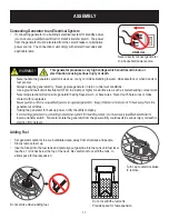
• Only operate generator on a level surface.
• Always connect the nut and ground terminal on the frame to an appropriate ground source.
WARNING!
Generator must be properly grounded to prevent electrocution.
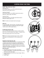
ON
OFF
Note:
The
Economy
switch must be turned to the “OFF” position when using electronic devices that require a large
starting current, such as a compressor.
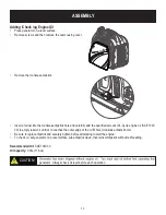
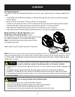
Parallel Outlets
Located just above the Ground Terminal, the generator’s Parallel Outlets enable a user to run two PG2300iS generator’s
simultaneously. This operation requires special cables. When operating parallel generators, the rated output is 3.42kVA and the
rated current is 30A/120VAC. For cables and instructions consult a PULSAR dealer for a PARALLEL OPERATION CABLE KIT.
• Only connect this generator to another PG2300iS
CO
Standard Generator.
• Only use a parallel operation cable kit designed to work with this Generator.
WARNING!
Never connect generators that are different models.


