


INSTALLATION
TM-5LC Super-Miniature Cylindrical CCD Camera
Page 5
2.2 Camera Setup
2.2.1 Power Cable
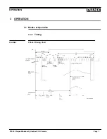
The TM-5LC has a power cable with color-coded flying leads attached to the back of the camera (see
Figure 3 in Appendix). The lead functions are as follows:
Lead Color
Function
Yellow
+12V DC
Gray
GND
White Coax
Video Out
Black
GND
2.2.2 Power Supply and Power Cable Setup
2.2.2 (a) Power Supplies
PULNiX recommends the following power supplies:
K25-12
110V AC/12V DC
2.1A power supply
P-15-12
220V AC/12V DC
2.1A power supply
K50-12
110V AC/12V DC
4.2A power supply
PD-12
110V AC/12V DC
0.5A power supply
PD-12U
90-220 AC/12V DC
1.2A power supply
2.2.2 (b) PD-12 Power Supply
When wiring the PD-12 power supply directly, please note the following:
•
The lead ends must be twisted together and tin-soldered for strength and electrical continuity.
•
Shrink tubing or a similar insulator should be used to prevent exposed leads from touching and
shorting.
•
The +12V lead is marked with a red stripe or white lettering; be sure not to reverse the leads.
•
All connections must be properly insulated to prevent shorting.
2.2.2 (c) “K” Series Power Supplies
The following procedure should be implemented to connect a “K” series power suply to the TM-5LC
camera:
1.
Attach the 110V line cord to the two terminals marked “AC”. Do not plug the cord into a 110V AC
socket until later in the procedure.
2.
Attach the gray and yellow leads of the power cable to the ground and 12V DC terminals, respec-
tively. Be sure to replace the plastic terminal guard on the power supply at this time.


