


3
6. MOUNTING INSTRUCTIONS
A trim ring is provided on the back of the Heat Alarm. This trim ring is removed by holding the trim ring and twist-
ing the Heat Alarm in the direction indicated by the TURN TO REMOVE arrow. The trim ring is secured to the
heat alarm by a trim lever.
CAUTION ! THE COVER IS A SEALED UNIT AND HAS NO REMOVABLE
SERVICEABLE PARTS ! DO NOT TAMPER.
6.1 Secure a suitable junction box near the position of the Heat Alarm, ensure the quick connect cable length
is long enough to reach the junction box for termination to be made.
6.2 Connect Active, Neutral and Switch line to the Heat Alarm cable using the terminal connection block pro-
vided. Secure these terminals inside the junction box.
6.3 Punch out the suitable fixing holes on the trim ring and then pull the AC connector through the centre of
the trim ring.
6.4 Secure the trim ring to the ceiling using the fixing holes provided.Connect the 9V battery (back up) into
the battery compartment. Now, plug in the AC connector into the back of the Heat Alarm. Ensure the
locks on the AC connector snaps firmly into place.
6.5 Now mount the heat alarm onto the trim ring. Rotate the heat alarm until the heat alarm snap firmly into
place.
NOTE:PLEASE ENSURE THAT BATTERY IS INSTALLED PRIOR TO MOUNTING OF HEAT ALARM
Switch on the A.C. power and the green A.C. power ‘ON’ indicator should be lit. The Heat Alarm is now operating
on mains power.
A
N
FUSE OR CIRCUIT BREAKER
RED
WHITE
BLACK
A
SW
N
RED
WHITE
BLACK
A
SW
N
RED
WHITE
BLACK
A
SW
N
RED
WHITE
BLACK
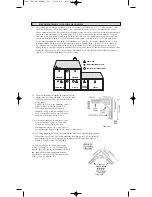
5.4 The maximum wire run distance between the first and last unit in an interconnected system is 307 metres.
Figure 1 illustrates interconnection wiring. Improper connection will result in damage to the alarm, failure
to operate, or electrical shock hazard.
5.6 Make certain alarms are wired to a continuous (non-switched) final sub-circuit.
Note: Use approved listed Australian Standards cable 1.0mm² TPS or larger as
required by local codes.
FIGURE 1 “INTERCONNECT WIRING DIAGRAM”
ALARM HARNESS --------------------CONNECTED TO:
BLACK
-------------------------------N
WHITE
-------------------------------SW
RED
-------------------------------A
FIGURE 1: TYPICAL DIAGRAM SHOWING INTERCONNECTION OPTIONS
1004-7201-01(HA240)_V2:_ 2010.9.2 9:20 AM Page 4


