background image

2. Upper Frame Fixings

Note: Refer to the Z-axis Z-axis-top parts section of the Prusa installation
guide   for   guidance   on   the   installation   and   re-installation   of   the   default
fixings, noting guidance on over tightening.

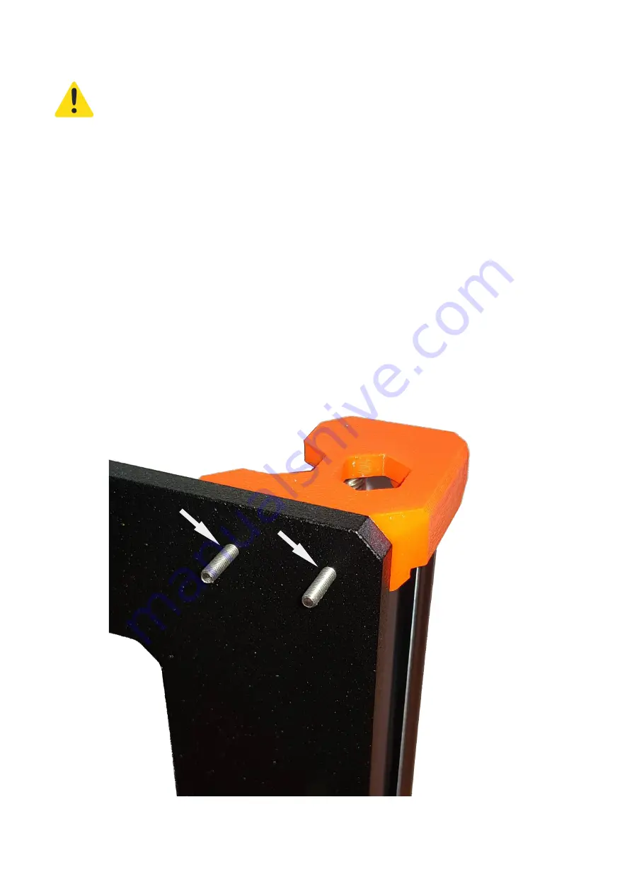
1. On the printer, adjust the X,Y,Z position of the head to x=150, y=0, z=60

2. Check the two Z-axis-top screws at the top of the frame on the left hand side and
ensure   they   are   not   loose   (i.e.   still   tightened   as   instructed   in   the   installation
manual)

3. Remove one of the screws (a) , and replace the 10mm M3 screw with a 20mm M3
screw using the guidance in the Prusa manual.

4. Once the first screw is tightened, use the same technique to replace the second
screw (b).

These two screws will be used to mount the Pi Box, along with a third (14mm) screw
which will be fitted from the other side.

- 5 -

b

a

Summary of Contents for i3 MK3S Multi Material Upgrade 2S

Page 1: ...f the frame at the rear above the Einsy control box It is secured by three bolts two of which replace the two M3 x 12 bolts holding the top of the left hand Z axis The Pi is powered from the 24V suppl...

Page 2: ...ircuits and potentially damage the printer or cause fire Use of tools can cause cuts burns etc Use of inappropriate wire types can cause shorts potentially damaging the printer or cause fire This is a...

Page 3: ...ase Shim Case Lid PSU Clip Pi3 or Pi4 Bezel Einsy Conduit Reset block optional Pi Connector Guide Einsy Connector Guide when connected via GPIO Non Printed Parts Raspberry Pi Memory Card 1 x 24V to 5V...

Page 4: ...m 2 Off M3 20mm 6 Off M3 30mm 2 Off M3 Hex Nut 5 Off M3 Square Nut 4 Off M2 8mm 4 Off M2 12mm for optional fan Tools 3mm Allen Key 2mm Allen Key Pliers Soldering Iron Crimp Tool for power cable Crimp...

Page 5: ...he two Z axis top screws at the top of the frame on the left hand side and ensure they are not loose i e still tightened as instructed in the installation manual 3 Remove one of the screws a and repla...

Page 6: ...Switch Block e The Pi Bezel f The Lid 4 Fitting The Anchor Shim The case has a separate anchor shim This allows custom conduits to be installed If no custom conduit is used then the shim can be used...

Page 7: ...he order of 250mA at 24V the cable should be sturdy enough to attach to the Einsy power supply terminals Make sure that the cable will fit through the hole in the case 2 Fit a fuse recommended in line...

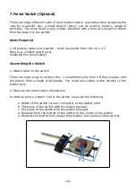
Page 8: ...Power Supply Module 24V 22mm x 17mm x 4mm 1 Make the measurements as shown in the figure below and plumb them into the model Hint measure the board after you have soldered any wires to it a Width of b...

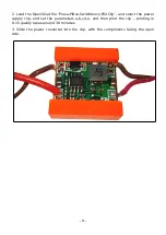
Page 9: ...tchblock PSUClip and select the power supply clip and set the parameters a b c d e and then print the clip printing in 0 15 quality takes around 30 minutes 3 Slide the power converter into the clip wi...

Page 10: ...bling the Switch 1 Attach wires to the switch There are many ways to achieve this I used 18mm pins from a Pi Zero header and the plastic from a single strip header You could also solder a wire directl...

Page 11: ...0 minutes 5 Insert the switch into the block until the button appears in the round hole Note that this should be a tight fit and you will have to press the button to perform the insertion If the switc...

Page 12: ...tivity these are not visible on the outside of the case An optional single colour LED can be installed which can be controlled by the GPIO Shutdown plugin this shows whether the OctoPi application is...

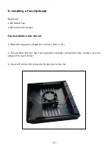
Page 13: ...f 12mm M2 Screws Fan Installation into the Lid 1 Note the required voltage for the fan 3 3V or 5V 2 Ensure that the fan has two separate terminal connectors the sockets are not adjacent to each other...

Page 14: ...fitted they will pass through the hole in the Pi Case 2 Thread the connectors through the case and down the cable sleeving alongside the power cable leaving an 80mm flying lead within the case Pi Conn...

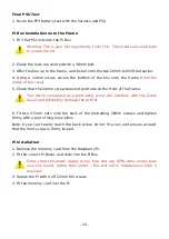
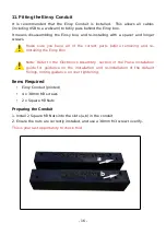
Page 15: ...of the frame This check is essential as a protruding screw will interfere with the Z Axis travel and potentially damage the printer 6 Fit two 3 5mm nuts onto the back of the protruding 20mm screws and...

Page 16: ...ing and re installing the Einsy Box Note Refer to the Electronics Assembly section of the Prusa installation guide for guidance on the installation and re installation of the default fixings noting gu...

Page 17: ...en the Einsy Lid and note the x y z e wire tags and if any are missing replace them before disassembly 5 Remove all connectors in the reverse order to that use to install it Refer to the Electronics A...

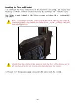
Page 18: ...crews as indicated in the assembly instructions Note The Conduit must be installed with threaded holes facing upwards and the the open side towards the metal frame to give the Einsy case and base a so...

Page 19: ...wer terminal a on the Einsy board This is the positive input power from the mains power supply unit 2 Undo the screw until the spade connector comes out 3 Place the positive spade connector from the P...

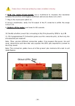
Page 20: ...1V 9 Switch off the mains and leave for 60 seconds 10 Decide whether you will be connecting to the Einsy board by GPIO or by USB 11 Fit the appropriate Pi Connection guide over the connector pins so...

Page 21: ...Note the leftmost two pins shown in the diagram should be disconnected these are for the fan positive supply 13 Double Check this orientation because incorrect orientation is likely to destroy the Pi...

Page 22: ...that the you should connect the following pins only a Ground b TxD c RxD d GPIO 23 e GPIO 24 Note also that the ground is connected to a different pin than that which is used with a direct connection...

Page 23: ...way around 19 If you have an LED this is connected to the LED GPIO connector b Note that in this case the orientation of the cable is important and the cathode of the LED must be connected to ground 2...

Page 24: ...sy Connection Guide Note that the you should connect the following pins only a Ground b TxD c RxD d GPIO 23 e GPIO 24 On no account should the 5V be connected between the Pi and the Einsy board the Pi...

Page 25: ...he fan is 3 3V connect the fan positive wire to the 3 3V pin on the expansion header 4 If the fan is 5V connect the fan positive wire to the 5V pin on the expansion header 5 Ensure that the cables are...

Page 26: ...6 Ensure the fan power cable is still attached and fit the lid and secure with three 20mm M3 screws 8 Finally close the door of the Einsy case and secure with its screw 26...

Page 27: ...password of raspberry ssh l pi octopi local b Launch the raspi config program sudo raspi config c In 5 Interfacing Options P6 Serial disable the login shell and enable the serial port hardware and ex...

Page 28: ...P 254 100 Temp PET 230 85 Temp FLEX 240 50 4 Perform a software update 5 Install the following plugins iponconnect used to allow the printer to report the IP details octolapse recommended but not requ...

Page 29: ...7 If Using GPIO Shutdown configure the plugin to use GPIO16 for the Shutdown and GPIO12 for the LED 29...

Page 30: ...en turning off the printer you should connect to the octopi local web server and shut down the Pi through the menu These instructions describe how to make the Pi memory card operating system partition...

Page 31: ...Notes Base No 30 Detail 0 1mm Lid No 30 Detail 0 1mm Anchor No 30 Detail 0 1mm Bezel Yes 30 Quality 0 15mm Print with front face downwards PSU Clip No 30 Detail 0 1mm Switch Block No 30 Detail 0 1mm...

Page 32: ...ther will damage both the Pi and the Einsy board 2 A connector may need soldering to the Pi for the hard reset In this instance it is likely to be difficult to solder the ground pin due to the thermal...

Page 33: ...C Pi Bezel Dimensions D Switch Block Dimensions E Power Clip Dimensions F Einsy Conduit Screw Fixing Dimensions 33...

Page 34: ...G Anchor Shim Dimensions Note Allowable tolerance is 0 05 on all dimensions To check 1 4 and 3 6 think they should be 1 5 and 3 5 34...

Reviews: