background image

Downloaded from Projector.com

ENGLISH-12

ENGLISH-12

O

O

O

O

P

P

P

P

E

E

E

E

R

R

R

R

A

A

A

A

T

T

T

T

II

II

O

O

O

O

N

N

N

N

S

S

S

S


((

((

c

c

c

c

o

o

o

o

n

n

n

n

tt

tt

ii

ii

n

n

n

n

u

u

u

u

e

e

e

e

d

d

d

d

))

))

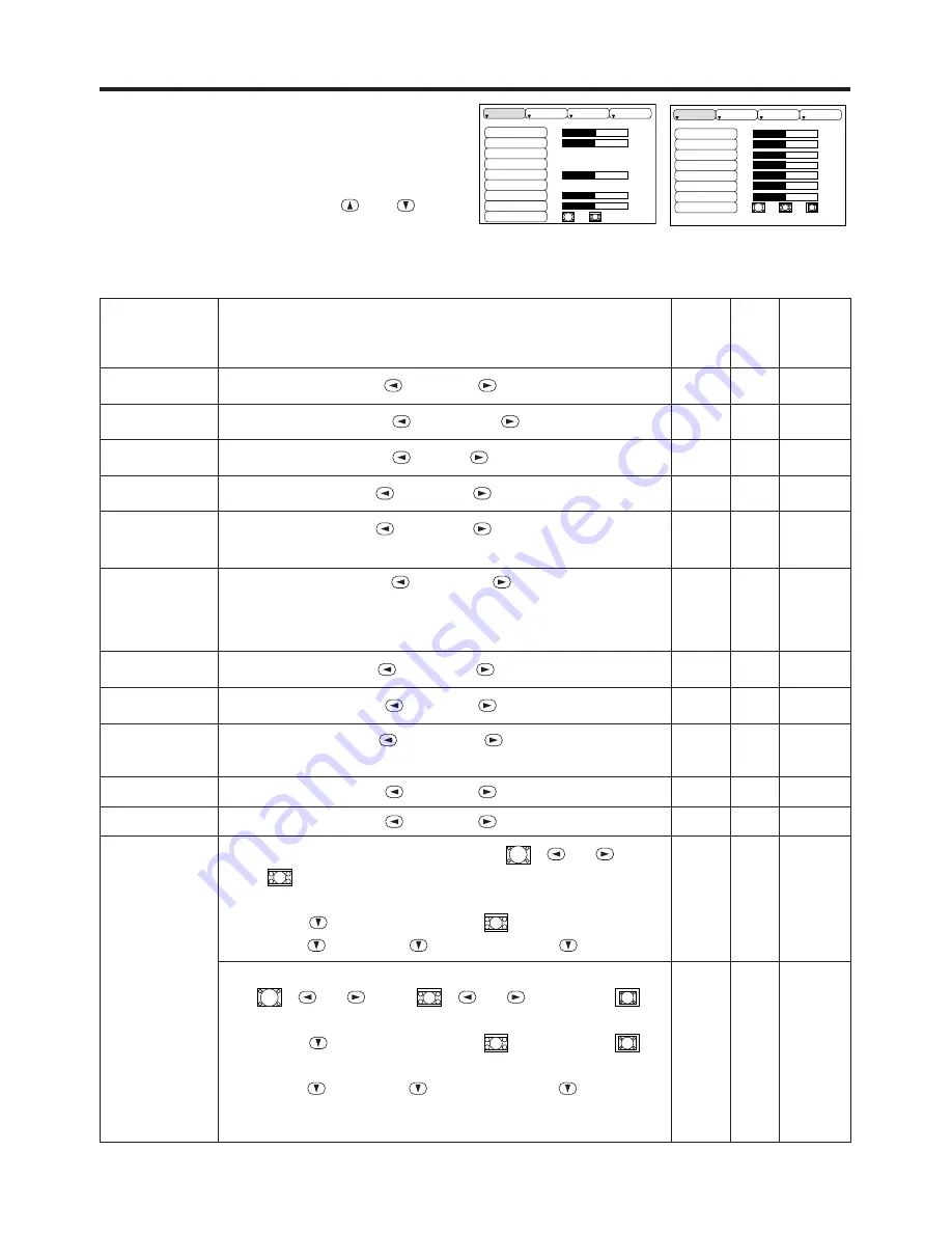
Setup Menu

The following adjustments and settings are possible
when SETUP is selected at the top of the menu. Part
of the Setup menu differs between RGB input and
video input. Select an item with the 

and

buttons, and start operation. Use the Single menu to
reduce menu size (see Table 3, MENU SELECT).

Table 4. Setup Menu

VIDEO

S-VIDEO

COMPONENT VIDEO

RGB IN 1
RGB IN 2

DIGITAL

BRIGHT

CONTRAST

V POSIT
H POSIT

H PHASE

H SIZE

COLOR BAL R
COLOR BAL B

ASPECT

0

-2

+1 

0
0

100
100

800

SETUP

INPUT

OPT.

IMAGE

BRIGHT

CONTRAST

SHARPNESS

COLOR

TINT

COLOR BAL  R
COLOR BAL  B

ASPECT

0

+1
+1

0
0
0
0

SETUP

INPUT

OPT.

IMAGE

Item

Description

RGB IN 1
RGB IN 2

DIGTAL

VIDEO

S-VIDEO

COMPONENT

BRIGHT

Adjustment: 

Dark 

Light 

CONTRAST

Adjustment:

Weak 

Strong 

V POSIT

Adjustment:

Down 

Up 

-

-

H POSIT

Adjustment:

Left 

Right 

-

-

H PHASE

Adjustment:

Left 

Right 

• Adjust to eliminate flicker.

-

-

H SIZE

Adjustment:

Small 

Large 

• The image may not be displayed correctly if the horizontal
size is excessive. In such cases, press the RESET button,
and initialize the horizontal size.

-

-

SHARPNESS

Adjustment:

Soft 

Clear 

-

-

COLOR

Adjustment:

Light 

Dark 

-

-

TINT

Adjustment:

Red 

Green 

• Valid only when NTSC or NTSC 4.43 signal is received.

-

-

COLOR BAL R

Adjustment:

Light 

Dark 

COLOR BAL B

Adjustment:

Light 

Dark 

ASPECT

Select Image Aspect Ratio :

4:3[

16:9[

]

Select Position of Image:

Press the 

button while 16:9[

] is selected.

Center

Down 

Up (

Center )

-

Select Image Aspect Ratio:

4:3[

16:9[

4:3 small[

]

Select Position of Image :

Press the 

button while 16:9[

] / 4:3 small[

]

is selected.
Center

Down

Up (

Center )

• 4:3 small may not be displayed correctly with some input
signals.

-

-

Summary of Contents for Desktop Projector 6860

Page 1: ...e do not make any claim of copyright The copyright remains the property of their respective owners ABOUT PROJECTOR COM Projector com http www projector com is your review and buying guide resource for DLP and LCD video projectors Visit the site to read the latest projector news and reviews read and comment on projector specifications download user manuals and much more ...

Page 2: ...88 1 800 294 6400 Fax 503 685 8887 In Europe Olympia l NL 1213 NS Hilversum The Netherlands Phone 31 35 6474000 Fax 31 35 6423999 Freephone 008000 4636287 008000 INFOCUS In Asia 238A Thomson Road 18 01 04 Novena Square Singapore 307684 Telephone 65 334 9005 Fax 65 334 4525 User s Guide 010 0298 00 Part No 010 0298 00 DP6860 User s Manual qxd Printed in Japan ...

Page 3: ...w n l o a d e d f r o m P r o j e c t o r c o P R ESEN TAT I ON SOL UT I ON S w w w p r ox i m a c o m 1 8 0 0 2 9 4 6 4 0 0 Desktop Projector DP6860 ...

Page 4: ... Table 8 No Signal Menu 16 Table 9 OSD Message 20 Table 10 Indicator Message 21 Table 11 Symptom 22 Table 12 Specifications 23 For TECHNICAL and REGULATORY NOTICE see the end of this manual The information in this manual is subject to change without notice The manufacturer assumes no responsibility for any errors that may appear in this manual The reproduction transmission or use of this document ...

Page 5: ...ilable BEFORE USE BEFORE USE Contents of package Make sure all of the following items are included in the package If anything is missing please contact your dealer Keep the original packing material for future reshipment NOTE Projector User s Guide this manual Safety Instruction Quick Start Guide Registration Card Power Cord US Type Power Cord Europe Type RGB Cable Video Audio Cable with white lea...

Page 6: ...O NENT VIDEO S VIDEO VIDEO MONO L AUDIO R CB PB CR PR DIGITAL USB ZOOM FOCUS MUTE INPUT MENU POWER TEMP LAMP STANDBY ON RESET ZOOM Button MUTE Button STANDBY ON Button LAMP Indicator POWER Indicator FOCUS Button INPUT Button MENU Button RESET Button TEMP Indicator Remote Control Sensor Lens Foot Adjuster Lens Cap Control Panel Ventilation Openings exhaust Carrying Handle Air Filter and Intake for ...

Page 7: ... LASER NON GUARDARE NEL RAGGIO LUCE APPARECCHIO LASER DI CLASSE 2 RAYONNEMENT LASER NE PAS REGARDER DANS LE FAISCEAU APPAREIL A LASER DE CLASSE 2 LASER STRAHLUNG NICHT IN DEN STRAHL BLICKEN LASER KLASSE2 MANUFACTURED PLACE OF MANUFACTURER A MADE IN JAPAN IEC60825 1 1993 A1 1997 STANDBY ON Button LASER Button BLANK Button Disk Pad Used to operate the mouse shift function and left click function AUT...

Page 8: ...omes difficult NOTE CAUTION Use only the specified batteries with this remote control transmitter Also do not mix new and old batteries This could cause battery cracking or leakage which could result in fire or personal injury When loading the batteries make sure the plus and minus terminals are correctly oriented as indicated in the remote control transmitter Incorrect orientation could cause bat...

Page 9: ...ers or cause the lock to fail Foot Adjusters The projection distances shown in the table below are for full size 1024 x 768 dots a Distance from the projector to the screen 10 b Distance from the lens center to the bottom of the screen 10 Table 1 Installation Reference b a Lens center Screen CAUTION Install the projector in a suitable environment according to instructions of the accompanying manua...

Page 10: ... be used with the core set to the projector side Use the cables which are included with the projector or specified Cabling Refer to the table below for connecting each terminal of the projector to each device Table 2 Cabling Function Terminal Cable Analog RGB input RGB IN 1 Accessory RGB cable or optional RGB cable with D sub 15 pin shrink jack and inch thread screws RGB IN 2 Analog RGB output RGB...

Page 11: ...may not operate by other connecting Plug play is a system configured with peripheral equipment including a computer and display and an operating system This projector is recognized as a plug play monitor Use the standard display drivers Plug play may not operate by the computer to connect Plug play will not operate in the connection with Apple computer NOTE NOTE ENGLISH 8 I I I IN N N NS S S ST T ...

Page 12: ...ON button has no effect while the POWER indicator is blinking 2 The system assumes the Standby mode when cooling is complete and the POWER indicator ceases blinking and changes to orange Check that the indicator is orange and set the Power switch to O 3 The POWER indicator is extinguished when power is off Attach the lens cap Power Switch Lens cap STANDBY ON Button POWER Indicator STANDBY ON LASER...

Page 13: ...ly 10 seconds of inactivity the icon is extinguished and the POSITION mode is cleared automatically and buttons may operate as the mouse control button Refer to page 4 RESET Initialise Each Item Select an item and press the RESET button Initialise Position Adjustment Press the RESET button and the POSITION mode This function is valid only when RGB signal is input Valid except for the VOLUME LANGUA...

Page 14: ...s terminated automatically after approximately ten seconds of inactivity MENU SELECT Select Menu Type Press the MENU SELECT button Allows the user to select the normal menu or the single menu Only the selected item is displayed on the single menu and other items are displayed with the and buttons as with the normal menu Valid only when the Setup menu is used Push the MENU SELECT button after selec...

Page 15: ...P INPUT OPT IMAGE Item Description RGB IN 1 RGB IN 2 DIGTAL VIDEO S VIDEO COMPONENT BRIGHT Adjustment Dark Light CONTRAST Adjustment Weak Strong V POSIT Adjustment Down Up H POSIT Adjustment Left Right H PHASE Adjustment Left Right Adjust to eliminate flicker H SIZE Adjustment Small Large The image may not be displayed correctly if the horizontal size is excessive In such cases press the RESET but...

Page 16: ...tical sync signal frequencies for RGB input Valid only at RGB input VIDEO Select Video Signal Type Select the signal type with the and buttons Select NTSC PAL SECAM NTSC4 43 M PAL or N PAL as appropriate for the input signal The selection of AUTO enables and executes the function AUTO Automatic Adjustment at Video Input except for the N PAL input Use this function when the image becomes unstable e...

Page 17: ...y not be displayed correctly with some input signals BLANK Select Blank Screen Color Select color with the and buttons The image is cleared when the BLANK mode is set with BLANK ON or when there is no signal and the entire screen is displayed in the selected color MIRROR Operation Start Stop Press the or button Select Mirror Status Select mirror status with and buttons START UP Operation Start Sto...

Page 18: ... the and buttons LANGUAGE Operation Start Stop Press the or button Select Menu Display Language Select with the and buttons AUTO OFF Operation Start Stop Press the or button Set AUTO OFF Set 1 99 minutes with the and buttons The system automatically enters the standby mode when a signal is not received for the set time Clear AUTO OFF Select STOP 0 min with the button When STOP is selected the syst...

Page 19: ...cleared and the complete screen is displayed in the selected color MIRROR Operation Start Stop Press the or button Select Mirror Status Select the mirror status with the and buttons START UP Operation Start Stop Press the or button Setup Initial Screen Display Select the TURN ON with the button Clear Initial Screen Display Select the TURN OFF with the button Note that if TURN OFF is selected the b...

Page 20: ...9 of P 20 and Table 10 of P 21 The LAMP indicator is also red when the lamp unit reaches high temperature Before replacing the lamp switch power OFF wait approximately 20 minutes and switch power ON again If the LAMP indicator is still red replace the lamp NOTE Lamp Front glasss Reflector WARNING For disposal of used lamp treat according to the instruction of community authorities Since the lamp i...

Page 21: ...de up Resetting the Lamp Timer Reset the lamp timer after replacing the lamp When the lamp has been replaced after the LAMP indicator is red or the CHANGE THE LAMP message is displayed complete the following operation within ten minutes of switching power ON The power will be turned off automatically in over 10 minutes 1 Switch power ON and press the RESET button for approximately three seconds Th...

Page 22: ...ily removed use a soft cloth dampened with water or water and a neutral detergent and wipe dry with a soft dry cloth CAUTION Switch power OFF and remove the power cord from the power outlet before beginning maintenance work Please read the separate SAFETY INSTRUCTIONS thoroughly to ensure that maintenance is performed correctly Do not use detergents or chemicals other than those noted above e g be...

Page 23: ... OFF AFTER hr 1 The lamp will reach the end of its life in hours Power will be switched OFF automatically in hours Replace the lamp as shown in P 17 18 Lamp Always reset the lamp timer after replacing the lamp CHANGE THE LAMP AFTER REPLACING LAMP RESET THE LAMP TIME THE POWER WILL TURN OFF AFTER 0 hr The lamp has reached the end of its life Power will be switched OFF in a few minutes Switch power ...

Page 24: ...20 minutes until the equipment cools and check whether the ventilation openings are blocked whether the air filter is dirty or whether the ambient temperature exceeds 35 C And switch power ON again Replace the lamp if the same problem occurs Lights red Blinks red Turns off Lamp or lamp cover is not found or hasn t been fitted in correctly Switch power OFF and wait for 45 minutes until the equipmen...

Page 25: ...0 No signal input Connect correctly 7 8 Video is present but no audio The projector is not correctly connected Connect correctly 7 8 The volume is set to minimum Press VOLUME on the remote control or display the menu screen and adjust the volume 11 15 Mute is turned on Press the MUTE button 11 Audio is present but no video The projector is not correctly connected Connect correctly 7 8 The brightne...

Page 26: ...omposite sync TTL level D sub 15 pin shrink jack 2 DIGITAL TMDS DC 150 1200 mV AC 1 56 Vp p TTL Level Positive Negative AUDIO IN RGB1 200mVrms 50 kΩ max 3 0Vp p Stereo mini jack DIGITAL RGB2 Video signal input VIDEO 1 0Vp p 75Ω terminator RCA jack S VIDEO Brightness signal 1 0Vp p 75Ω terminator Color signal 0 286Vp p burst signal 75Ω terminator Mini DIN 4 pin jack COMPONENT VIDEO Y 1 0 Vp p 75 Ω ...

Page 27: ...LISH 24 WARRANTY AND AFTER SERVICE WARRANTY AND AFTER SERVICE If a problem occurs with the equipment first refer to the P 20 TROUBLESHOOTING section and run through the suggested checks If this does not resolve the problem contact your dealer or service company ...

Page 28: ...e do not make any claim of copyright The copyright remains the property of their respective owners ABOUT PROJECTOR COM Projector com http www projector com is your review and buying guide resource for DLP and LCD video projectors Visit the site to read the latest projector news and reviews read and comment on projector specifications download user manuals and much more ...

Reviews: