Operation and
Installation Guide
24 KKV
28 KKV
28 KKO
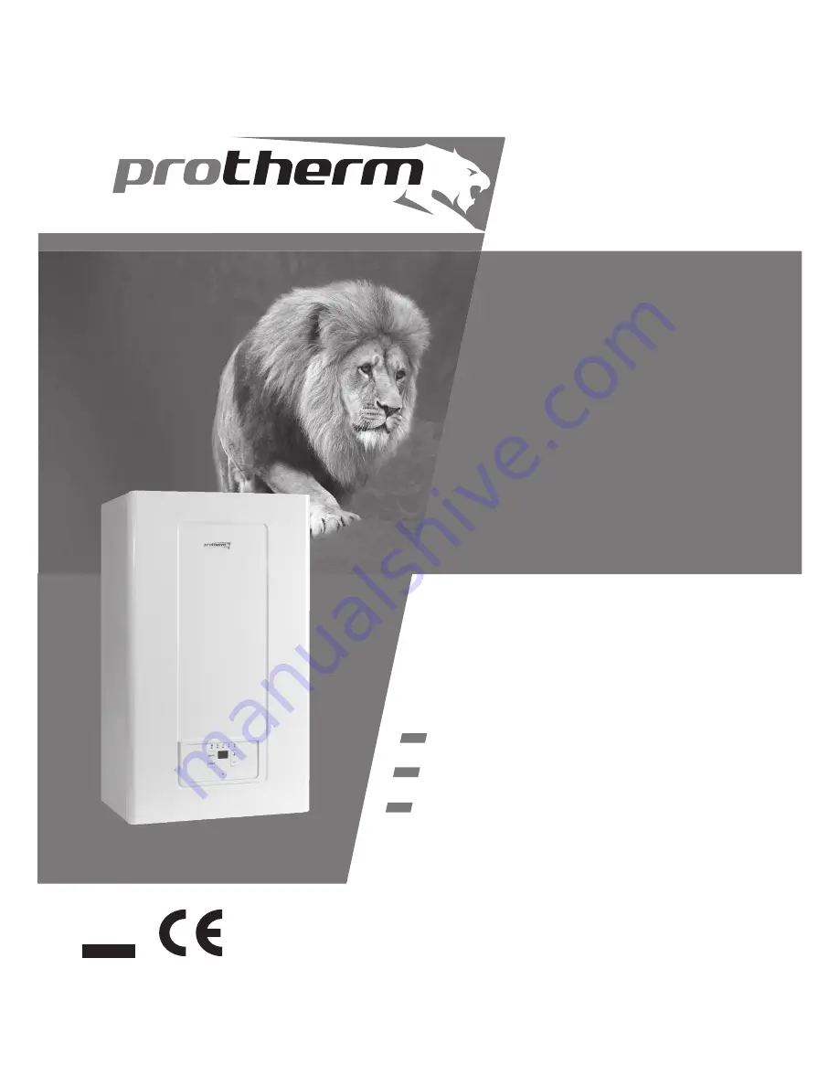
Wall-mounted condensing boiler
Output range 5 - 27,9 kW / 5,7 - 31,7 kW
Hot water heating (24 / 28 KKV)
Lion
xxxxxxxxxx_00- v.1 7/2007
EN
v e r s i o n
Page 1: ...Operation and Installation Guide 24 KKV 28 KKV 28 KKO Wall mounted condensing boiler Output range 5 27 9 kW 5 7 31 7 kW Hot water heating 24 28 KKV Lion xxxxxxxxxx_00 v 1 7 2007 EN ve r s i o n...
Page 2: ...r installation 22 Installing the boiler 24 Air supply and ue gases removal 28 Components of concentric 60 100 ue gas removal 32 Components of concentric 80 125 ue gas removal 33 Components of separate...
Page 3: ...blic When used in the conditions of other countries any deviations from local regulations must be identi ed and recti ed 6 In the event of a defect call a manufacturer s service organisation any unaut...
Page 4: ...ed for Type C gas appliances i e in closed execution the so called TURBO In addition to the above mentioned documents it is necessary when using the boiler to proceed in accordance with this Operation...
Page 5: ...you can monitor instantaneous values and set the required parameters Description of control elements Fig 1 Fig 1 1 2 3 4 5 6 7 8 9 11 10 2 Heating water LED indicates display mode or setting of heati...
Page 6: ...ler will heat only hot water i e it will be working in the so called summer mode Displaying heating water temperature After turning the boiler on with the main switch the current heating water tempera...
Page 7: ...burner failed to ignite Check the gas shutting valve underneath the boiler and press the RESET button If the fault persists call an authorised service Please note The boiler will make ve attempts to...
Page 8: ...Setting hot water temperature COMFORT hot water heating mode Warning heating water pressure too low Error code displayed Service required message By pressing RESET try to restart the boiler If the pro...
Page 9: ...r down take into consideration the ambient temperature in the given season If there is a danger that the boiler may freeze drain the water from the boiler the heating system and the hot water pipes St...
Page 10: ...re in hot water tank drops to 10 C the boiler heats the tank to 15 C The function is enabled only when the external hot water tank with an NTC sensor is connected Protective functions Pump protection...
Page 11: ...g conditions must be met 1 Pressure of the water supplied to the boiler must be always higher than the water pressure inside the heating system instructions in section Starting the boiler and turning...
Page 12: ...Position 4 and the display shows current heating water pressure partially open the top up valve Fig 3 Watch the pressure grow on the boiler s display panel ll the system up until the pressure reaches...
Page 13: ...1 2 2 Thermal range C 35 87 Expansion vessel l 10 Boiler water volume heating water volume l 2 7 Max pressure in expansion vessel bar 3 Domestic hot water HW Max supply pressure bar 6 Min supply pres...
Page 14: ...ar 1 2 2 Thermal range C 35 87 Expansion vessel l 10 Boiler water volume heating water volume l 2 7 Max pressure in expansion vessel bar 3 Domestic hot water HW Max supply pressure bar 6 Min supply pr...
Page 15: ...Heating Max operating pressure bar 3 Min operating pressure bar 0 6 Recommended operating pressure bar 1 2 2 Thermal range C 35 87 Expansion vessel l 10 Boiler water volume heating water volume l 2 7...
Page 16: ...utlet 3 4 2 HoW inlet 3 4 KKV only 6 Condensate outlet 19 mm 3 Gas inlet 3 4 7 Safety valve overflow 15 mm 4 HoW outlet 3 4 KKV only Bypass opening pressure is set to 25 kPa setting range 17 35 kPa 0...
Page 17: ...ing valve 23 HoW NTC sensor 3 expansion vessel 13 back ow valve 24 HeW pressure sensor 4 exchanger 14 top up valve 25 trap 5 pump air bleeding valve 15 lter 26 HoW exchanger lter 6 pump 16 HeW inlet 2...
Page 18: ...20 lter 3 expansion vessel 12 HeW inlet into the tank 21 gas valve 4 exchanger 13 gas inlet 22 fan 5 pump air bleeding valve 14 HeW outlet from the tank 23 burner 6 pump 15 HeW outlet 24 HeW temperatu...
Page 19: ...with a bath tub or shower and washing rooms according to STN 33 2000 7 701 they may not be installed in zone 0 Fig 8 When installed in one of the above rooms the boiler must have a protection against...
Page 20: ...ler upper parts particularly the side walls and the cover of a working boiler might exceed the ambient temperature by up to 50 C The manipulation free space left around the boiler must be suf cient fo...
Page 21: ...20 Fig 10 1 2 3 6 5 4 7 8 14 9 10 11 12 15 16 17 18 13 Content of delivery Completeness of delivery...
Page 22: ...User s Guide 15 Warranty Certi cate 16 List of service centres 17 Service Book Special accessories The following special accessories can be ordered as required 1 Connection ramp Order No 0020038446 Fi...
Page 23: ...radiators particularly in gravity systems In new systems it is necessary to remove all conservation material which majority of radiator manufacturers use It is recommended to install upstream the boi...
Page 24: ...ge of 1 to 6 bar If the pressure exceeds 6 bar a pressure reduction valve must be tted on the supply side combined with a safety valve In areas with very hard water we recommend to implement suitable...
Page 25: ...ith the screws provided 7 Mount the boiler K on the mounting bar L 8 Install adapter A to the boiler and tubing for combustion gases exhaust O Fill the space between the tubing and the wall with non c...
Page 26: ...s well as the gas supply by exible hoses but only those designed for that purpose Flexible componentsshouldbeasshortaspossible must be protected against mechanical and chemical loads and damage and mu...
Page 27: ...valve being clogged with dirt from the heating system are not covered by the boiler s warranty Connecting gas supply The Lion boilers are designed to be fuelled by natural gas of nominal pressure in t...
Page 28: ...ecessary to keep removing con densate from the boiler all the time and hence the boiler is equipped wit a con densate trap situated in its bottom secti on Condensate removal hose must have a minimum d...
Page 29: ...mitted tube lengths Unless stated for the following dual tube route design methods and their termination outlets otherwise the tube lengths from the boiler connection point to the termination outlet m...
Page 30: ...t be terminated at mutually opposite building walls Method C83 tubing with the air supply part terminated in free space and the combustion gases part in a common chimney Air may also be taken from fre...
Page 31: ...t be located in the following places with the danger of explosion as de ned by STN 33 2320 in the building s interior attics corridors staircases etc which can be closed e g in gateway passages etc un...
Page 32: ...wall are a 0 5 m b 1 0 m c 5 0 m a1 depen ding on x as follows x 5 0 m is a1 0 5 m x 4 0 m is a1 0 6 m x 3 0 m is a1 0 75 m x 2 0 m is a1 1 0 m x 1 0 m is a1 1 2 m Fig 24 Dual outlet with vertical arr...
Page 33: ...ction to the boiler s 60 100 mm concentric neck Please note You must start with this component Subassembly parts 1 adapter 1 60 mm sealing ring 1 100 mm sealing ring Length 145 mm Pressure loss 0 2 Em...
Page 34: ...the boiler s 60 100 mm concentric neck Please note You must start with this component Subassembly parts 1 60 100 80 125 mm adapter 1 80 mm sealing ring 1 125 mm sealing ring Length 142 mm Pressure lo...
Page 35: ...ic 80 125 mm supply and flue tubing If it is necessary to shor ten the tube saw off the end without a neck Subassembly parts 1 80 mm supply tube 1 125 mm flue tube 1 80 mm sealing ring 1 125 mm sealin...
Page 36: ...supply ue tube route For passage through the roof use the roof tile manufacturer s roof passage transition piece The subassembly must be complemented with an RM12M adapter for sealing the outside int...
Page 37: ...ing adapter with reading points 1 splitting adapter support 1 sealing ring for the boiler air section 2 80 mm sealing ring Speci cation of separate 80 80 ue components R2M Splitting adapter 2 80 Item...
Page 38: ...ue tube route direction by 45 Please note When connecting two elbows in a sequence 1 0 Em pressure loss must be allowed for each elbow It is therefore recommended to install 0 5 straight tube section...
Page 39: ...ressure loss 1 5 Em S21M Chimney subassembly 80 125 mm Item No 7747 SR2 silicon disc 80 mm Item No 2927 Description The disc is used to seal and aesthetically cover penetration of separate 80 mm intak...
Page 40: ...m Item No 7756 Description A bracket for attaching an 80 mm tube to the wall Subassembly parts 3 80 mm pipe bracket Z2K Tube end cage 80 mm Item No 300941 Description Muzzle for insertion on the end o...
Page 41: ...be always connected to the protection wire earth through its power cord and must be always installed in such a way that the Elektrick pripojenie kotla Fig 25 Wiring room control unit KOTEL Room therm...
Page 42: ...by a two core cable The recommended copper wire cross section is between 0 5 and 1 5 sq mm The room control unit connection cable must not run in parallel with power wires or cables The terminal box...
Page 43: ...ernative fuel propane The Protherm Lion 28 24 KKV and 28 KKO boilers are as standard made to run on natural gas If it is required that the boiler is run on propane it has to be con verted for this typ...
Page 44: ...C Tank Pump Ignition electrode 1 2 ZIG ignition transformer GND Vall 4 3 GND Testing programming interface TRAFO TOP sensor blue X2 8 red X2 7 red X2 5 1 1 2 2 blue white X32 1 X32 2 eBUS Fan Gas valv...
Page 45: ...2 2 X32 1 X32 2 eBUS 1 1 re X20 18 9 bl X20 9 1 X20 17 2 X20 3 4 X20 4 5 X20 16 1 Protherm user interface 1 1 X51 1 GND 2 X51 2 reset 4 X51 4 5 VDC 5 X51 5 24 VDC 6 X51 6 P eBUS 3 3 4 4 1 1 1 X2 12 s...