Protek 1006 User Manual Download Page 9


To compensate probes 

Perform this adjustment to match the characteristics of the probe and the channel input. 
This should be performed whenever attaching a probe to any input channel the first time. 


1.  From CH1 menu, set the Probe attenuation to 10X (press CH1

Probe

10X). 

Set the switch to 10X on the probe and connect it to CH1 of the scope meter. 
When using the probe hook-tip, inserting the tip onto the probe firmly to ensure a 
proper connection. 
Attach the probe tip to the Probe compensator connector and the reference lead to the 
ground pin, Select CH1, and then press AUTO. 

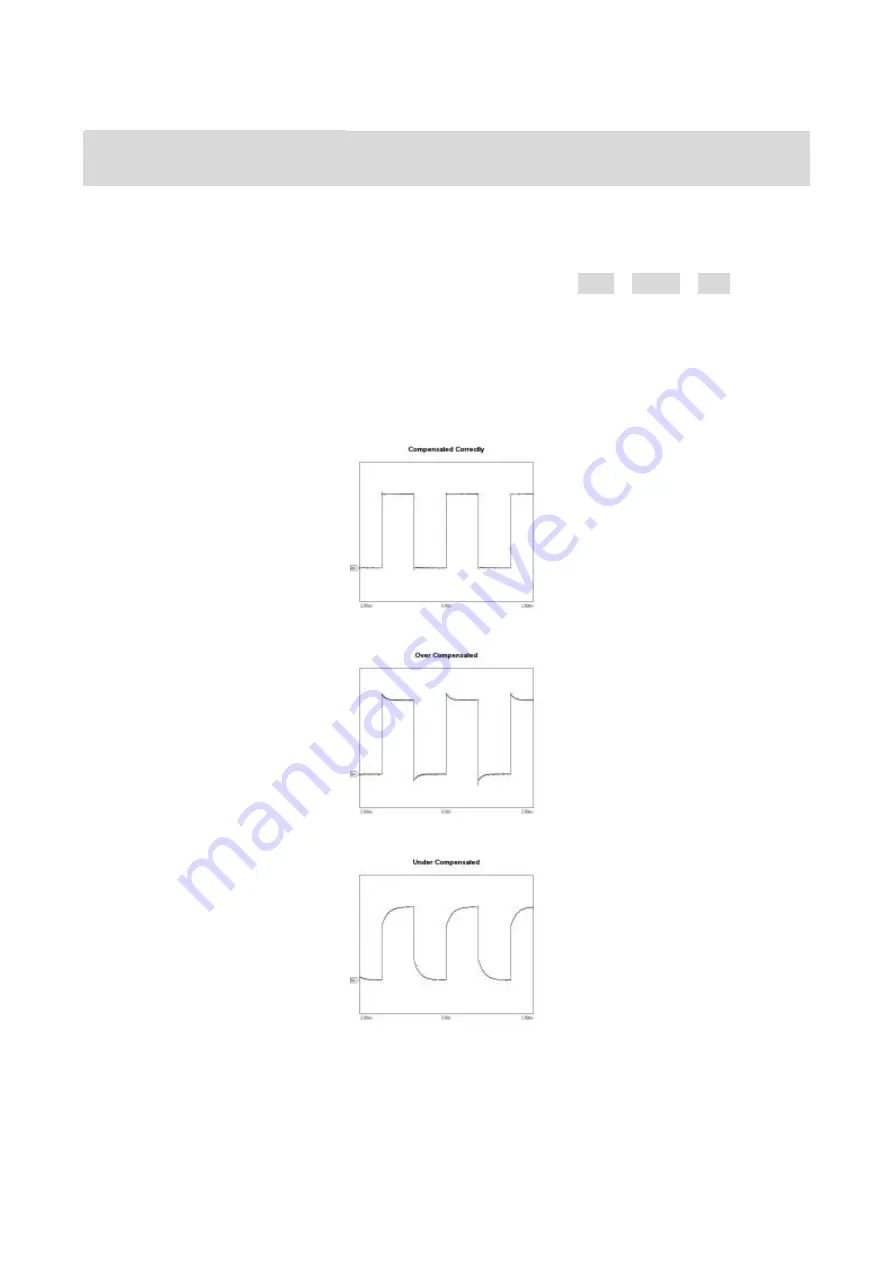
2.  Check the shape of the displayed waveform. 


Correctly Compensated 


Over compensated 


Under Compensated 


3.

  If necessary, use a non-metallic tool to adjust the trimmer capacitor of the probe for the 

flattest square wave being displayed on the oscilloscope


4.  Repeat if necessary. 


Summary of Contents for 1006

Page 1: ...Protek 1000 Handheld Scope Meter Series USER S MANUAL 1006 1020 1160 1260 ...

Page 2: ...t or other property might occur Symbols on the Product These symbols may appear on the product 2 General Safety Information Carefully read the following safety information in order to avoid any personal injury or damage on this product or any products connected with it Review the following safety precautions carefully before operate the device to avoid any personal injuries or damages to the devic...

Page 3: ...her ratings information before making connections to the product Use Proper Probe To avoid shock hazard use a properly rated probe for your measurement Avoid Circuit or Wire Exposure Do not touch exposed connections and components when power is on Do Not Operate With Suspected Failures If suspected damage occurs with the device have it inspected by qualified service personnel before further operat...

Page 4: ...ixels resolution USB storage and printing supports firmware upgrade via USB interface Adjustable waveform intensity more effective waveform viewing One touch automatic setup ease of use AUTOSET 15 Waveforms 15 setups supports CSV and bitmap format 20 Automatic measurements Automatic cursor tracking measurements Waveform recorder record and replay dynamic waveforms User selectable fast offset calib...

Page 5: ...this chapter carefully before further operations Front Panel Figure 1 1 The buttons allow you to use some of the functions directly but also bring up the manual keys on the screen which enable the access to many measurement features associated with advanced functions mathematics and reference or to run control features Figure 1 1 Protek1000 Series H H Scope Meter Front Panel ...

Page 6: ...loscope operation mode 9 TIME DIV Decrease or Increase the time base 10 POSITION Adjust the horizontal trigger position 11 CH2 Shows the CH2 menu 12 VOLTS Decrease or Increase the voltage div 13 CH1 Shows the CH1 menu 14 M R Shows the Math or REF menu 15 DMM Buttons The DMM control buttons 16 DMM SCOPE Switch DMM or Scope function 17 MENU ON OFF Turn on off the menu 18 SAVE RECALL Shows SAVE or RE...

Page 7: ...hows the trigger mode 6 Shows the trigger source 7 Shows the trigger level 8 Shows the power 9 The center of current waveform window 10 CH1 waveform 11 The trigger level symbol 12 The grid 13 CH2 waveform 14 Shows the time base 15 Shows the menu title 16 The menu 17 CH1 CH2 18 Shows the coupling 19 Shows the voltage div 20 CH2 mark 21 CH1 mark 22 Shows the trigger position in current waveform wind...

Page 8: ...ttenuation switch on the probe to 10X and connect the probe to Channel 1 on the scope meter To do this Align the slot in the probe connector with the key on the CH 1 BNC connector Push to connect and twist to the right to lock the probe in place Attach the probe tip and ground lead to the PROBE COMP connector Set the probe attenuation of the scope meter to 10X To do this push CH1 Probe 10X Figure ...

Page 9: ...H1 of the scope meter When using the probe hook tip inserting the tip onto the probe firmly to ensure a proper connection Attach the probe tip to the Probe compensator connector and the reference lead to the ground pin Select CH1 and then press AUTO 2 Check the shape of the displayed waveform Correctly Compensated Over compensated Under Compensated 3 If necessary use a non metallic tool to adjust ...

Page 10: ...onnect a signal to the channel 1 input 1 Connect a signal to the scope meter 2 Press AUTO The scope meter may change the current setting to display the signal It will automatically adjust the vertical and horizontal scaling the trigger coupling type position slope level and mode settings Using the Scope Meter This part provides a step by step introduction to the scope meter functions The introduct...

Page 11: ... of the screen and the corresponding optional settings on the bottom Press MENU ON OFF again will hide the Function Menu 2 Choose one key from F1 to F5 and press it to change function setting To set up the vertical system 1 Change the vertical setup and notice that each change affects the status bar differently Change the vertical sensitivity with or button and notice the change in the status bar ...

Page 12: ...g the location of the trigger level 2 Change the trigger setup and notice these changes in the status bar Press TRIG button in the key panel Choose one key from F1 to F5 and press it to change function setting 3 Press 50 The 50 button sets the trigger level to the center of the signal Specifications Vertical Channels 2 Bandwidth Protek1006 60MHz Protek1020 200MHz Protek1160 600MHz Protek1260 600MH...

Page 13: ...th Alternative Video X Y Mode X Axis Input Channel 1 Y Axis Input Channel 2 Phrase Shift Max 3 degree Cursors and Measurement Voltage Vpp Vamp Vmax Vmin Vtop Vmid Vb ase Vavg Vrms Vcrms Preshoot Overshoot Time Frequency Rise time Fall Time Postive Width Negative Width Duty Cycle Delay Delay 1 2 Delay 1 2 Cursors Manual Track Auto Measure Modes Math Addition Subtraction Multiplication Division FFT ...

Page 14: ...rtical X 320 Horizontal Dots INTERFACE USB USB host Device 2 0 Full Speed Supported Optional RS232 LAN POWER SOURCE Line Voltage Range AC 100V 240V 50Hz 60Hz DC Input 8 5 VDC 1500mA Battery Power Installed 6 hours Li ion Battery MECHANICS Dimension 245 x 163 x 52 mm Weight 1 2Kgs Other GND Reference scope meter and multimeter Independence ...

Reviews: