background image

Chapter  5  BIOS  Setup 

PA-3222 SERIES USER MANUAL


Page: 5-28


BIOS Setting 

Options 

Description/Purpose 

Device reset time-out 

10 / 20 / 30 / 40 
sec 

USB mass storage device Start Unit 
command time-out. 

Device power-up delay 

- Auto
- Manual

Maximum time the device will take before 
it properly reports itself to the Host 
Controller. 'Auto' uses default value: for a 
Root port it is 100 ms, for a Hub port the 
delay is taken from Hub descriptor. 

Device power-up delay in 
seconds 

multiple options 
ranging from 0 to 
40 

Delay range is from 1 to 40 seconds, in 
one second increments 

5.5  Chipset 

Menu Path 

Chipset 

This menu allows users to configure advanced Chipset settings such as 

North Bridge


and 

South Bridge

 configuration parameters. 

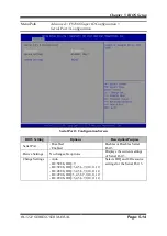
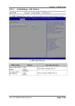
Chipset Screen 

Summary of Contents for PA-3222

Page 1: ...USER MANUAL PA 3222 10 1 POS Terminal Powered by Intel Celeron J1900 Quad Core PA 3222 M1...

Page 2: ...t in any form or by any means electronic or mechanical including photocopying and recording DISCLAIMER This user s manual is meant to assist users in installing and setting up the system The informati...

Page 3: ...rference at his own expense You are cautioned that any change or modifications to the equipment not expressly approve by the party responsible for compliance could void your authority to operate such...

Page 4: ...View 2 3 2 2 3 Top View 2 4 2 2 4 Bottom View 2 5 2 2 5 Quarter View 2 5 2 2 6 Side View 2 6 2 3 System Views With i Button Module 2 7 2 3 1 Front View 2 7 2 3 2 Rear View 2 7 2 3 3 Top View 2 8 2 3 4...

Page 5: ...on Buttons and I O Ports 3 8 3 5 1 Power Button 3 8 3 5 2 DC_IN Port DC_IN 3 8 3 5 3 VGA Port VGA 3 8 3 5 4 COM Ports COM1 COM2 COM3 3 9 3 5 5 USB Ports USB0 USB1 USB2 USB3 USB5 3 10 3 5 6 LAN Port LA...

Page 6: ...SATA_PWR1 SATA_PWR2 3 26 3 6 18 BIOS Update Selection JP1 3 27 3 6 19 Clear CMOS Data Selection JP2 3 27 3 6 20 LVDS Link JP16 3 28 3 6 21 LVDS Voltage Selection JP17 3 28 3 6 22 Panel Enable Selecti...

Page 7: ...Connector Quick Reference Table 3 45 3 7 7 Setting Printer Board Connectors and Jumpers MB 1011 MB 1013 3 46 3 7 7 1 Power Supply Connector 3 46 3 7 7 2 RS 232 Interface Connector 3 46 3 7 7 3 Auto C...

Page 8: ...Driver Utility 4 4 4 5 Installing Sound Driver Utility 4 6 4 6 Installing Fingerprint Driver Utility Optional 4 7 4 7 Installing RFID Module Driver Utility Optional 4 7 4 8 Installing Wireless Module...

Page 9: ...on 5 2 5 2 Accessing Setup Utility 5 3 5 3 Main 5 7 5 4 Advanced 5 9 5 4 1 Advanced ACPI Settings 5 10 5 4 2 Advanced F81866 Super IO Configuration 5 11 5 4 3 Advanced Hardware Monitor 5 17 5 4 4 Adva...

Page 10: ...or System LCD Panel A 5 Exploded Diagrams For System LCD Panel A 6 Exploded Diagrams For System LCD Panel A 7 Exploded Diagram For HDD A 8 Exploded Diagram For MSR Module A 9 Exploded Diagram For Fing...

Page 11: ...viii Configuring WatchDog Timer B 10 Flash BIOS Update B 13...

Page 12: ...ix Revision History The revision history of PA 3222 User Manual is described below Version No Revision History Page No Date M1 Initial Release 2017 05 10...

Page 13: ...3222 SERIES USER MANUAL Page 1 1 1 Introduction This chapter provides the introduction for the PA 3222 system as well as the framework of the user manual The following topic is included About This Man...

Page 14: ...pecifications and illustrates the physical appearances for the PA 3222 system Read the safety reminders carefully on how to take care of your system properly Chapter 3 System Configuration This chapte...

Page 15: ...222 system It describes how to set up the system quickly and outlines the system specifications The following topics are included Package List System Overview System Diagrams System Specification Safe...

Page 16: ...the items listed below are damaged or list please contact your local distributor immediately Item Q ty PA 3222 1 Manual Driver DVD 1 Quick Reference Guide 1 AC Power Cord Optional 1 MSR Card Reader O...

Page 17: ...Chapter 2 Getting Started PA 3222 SERIES USER MANUAL Page 2 3 2 2 System Views Without i Button and Fingerprint Modules 2 2 1 Front View Unit mm 2 2 2 Rear View Without i Button Without Fingerprint...

Page 18: ...Chapter 2 Getting Started PA 3222 SERIES USER MANUAL Page 2 4 2 2 3 Top View Without i Button 298 29 299 88 Without i Button...

Page 19: ...Chapter 2 Getting Started PA 3222 SERIES USER MANUAL Page 2 5 2 2 4 Bottom View 2 2 5 Quarter View Without i Button...

Page 20: ...Chapter 2 Getting Started PA 3222 SERIES USER MANUAL Page 2 6 2 2 6 Side View Unit mm Without Fingerprint module 147 75 Without Fingerprint...

Page 21: ...Chapter 2 Getting Started PA 3222 SERIES USER MANUAL Page 2 7 2 3 System Views With i Button Module 2 3 1 Front View 2 3 2 Rear View...

Page 22: ...Chapter 2 Getting Started PA 3222 SERIES USER MANUAL Page 2 8 2 3 3 Top View With i Button 299 87 298 29 With i Button...

Page 23: ...Chapter 2 Getting Started PA 3222 SERIES USER MANUAL Page 2 9 2 3 4 Bottom View 2 3 5 Quarter View With i Button...

Page 24: ...Chapter 2 Getting Started PA 3222 SERIES USER MANUAL Page 2 10 2 3 6 Side View 147 75...

Page 25: ...Chapter 2 Getting Started PA 3222 SERIES USER MANUAL Page 2 11 2 4 System Views With Fingerprint Module 2 4 1 Front View 2 4 2 Rear View...

Page 26: ...Chapter 2 Getting Started PA 3222 SERIES USER MANUAL Page 2 12 2 4 3 Top View...

Page 27: ...Chapter 2 Getting Started PA 3222 SERIES USER MANUAL Page 2 13 2 4 4 Bottom View 2 4 5 Side View 147 10 With Fingerprint...

Page 28: ...SB 3 x USB 2 0 and 1 x USB 3 0 on rear 1 x USB 2 0 on side bezel Serial Ports 3 x RJ45 all support 5V 12V selectable 1 optional x DB9 LAN 1 x RJ45 VGA 1x DB15 Cash Drawer 1 1 option with Y cable x RJ1...

Page 29: ...Chapter 2 Getting Started PA 3222 SERIES USER MANUAL Page 2 15 Environment EMC Safety CE FCC Operating Temp 0 C 35 C 32 F 95 F Storage Temp 5 C 60 C 23 F 140 F Humidity 20 90...

Page 30: ...m a hot place to a cold place and vice versa because condensation may occur inside the system Protect your PA 3222 from strong vibrations which may cause hard disk failure Do not place the system too...

Page 31: ...he following topics are included System External I O Ports Diagram Function Buttons and I O Ports Main Board Component Locations Jumper Settings Setting Jumpers Setting Main Board Connectors and Jumpe...

Page 32: ...UAL Page 3 2 3 1 External System I O Ports Diagram Pin Assignment 3 1 1 Rear I O Ports Diagram Side I O Power USB5 Button Option 3 DRW1 DRW1 1 DRW1 2 extended with Y cable LAN USB 1 2 3 COM4 VGA USB0...

Page 33: ...rawer Control Selection JP15 LVDS Link JP16 LVDS Voltage Selection JP17 Panel Enable Selection JP20 System CONNECTOR Description NAME COM Ports and Cash Drawer Port COM2 COM3 COM1 COM4 DRW1 COM Connec...

Page 34: ...Chapter 3 Hardware Configuration PA 3222 SERIES USER MANUAL Page 3 4 3 3 Component Locations Of System Main Board 3 3 1 Top View of System Main Board Figure 3 1 Main Board Component Location Top View...

Page 35: ...y grounded CAUTION Observe precautions while handling electrostatic sensitive components Make sure to ground yourself to prevent static charge while you are working on the connectors and jumpers Use a...

Page 36: ...s by opening or closing jumpers Jumpers can be combined into sets that are called jumper blocks When jumpers are all in the block you have to put them together to set up the hardware configuration The...

Page 37: ...Chapter 3 Hardware Configuration PA 3222 SERIES USER MANUAL Page 3 7 Jumper diagrams Jumper settings...

Page 38: ...T Press 0V Release 3 3V 3 5 2 DC_IN Port DC_IN Port Name DC_IN Description DC Power In Port rear I O PIN ASSIGNMENT PIN ASSIGNMENT 1 GND 3 24V 2 GND 4 24V 3 5 3 VGA Port VGA Port Name VGA Description...

Page 39: ...urrent 1A 5 GND Note COM2 COM2_1 will not function when jumpers JP10 JP11 JP12 are set as 2 3 connected i Button Refer to the i Button Function Selection section for details COM4 will not function whe...

Page 40: ...6 LAN Port LAN Port Name LAN Description LAN RJ 45 Port rear IO PIN ASSIGNMENT PIN ASSIGNMENT 1 MDIP0 5 MDIP2 2 MDIN0 6 MDIN2 3 MDIP1 7 MDIP3 4 MDIN1 8 MDIN3 LAN LED Status There are LAN LED indicato...

Page 41: ...tion PA 3222 SERIES USER MANUAL Page 3 11 3 5 7 Cash Drawer Port DRW1 Port Name DRW1 Description DRW1 is used by default PIN ASSIGNMENT 1 DRW2 Sense 2 GPIO1 DRW1 3 Draw1 Sense 4 12V 24V Max current 1A...

Page 42: ...5V 12V Selection JP_COM2 JP_COM3 Pin headers on board The voltages of both COM2 COM3 ports can be adjusted by setting relevant jumpers on board SELECTION JUMPER SETTING JUMPER ILLUSTRATION RI 1 2 Defa...

Page 43: ...t 1A 5 GND 10 NC 3 6 3 i Button Connector I BUT Connector Name I BUT Description i Button Connector PIN ASSIGNMENT 1 COM3_DTR_R_I 2 COM3_RXD_R_I 3 6 4 COM2 i Button Function Selection JP10 JP11 JP12 J...

Page 44: ...s below Method 1 DRW1 includes two groups of GPIO pins The second group is normally unused but can be enabled by the jumper Set the pin header jumper JP15 as 1 2 connected if necessary Method 2 You ca...

Page 45: ...re Configuration PA 3222 SERIES USER MANUAL Page 3 15 Step 3 DRW1 DRW1 1 DRW1 2 shares the same power source Default 12V SIO Address Cash drawer 1 LDN 06 0x91 bit 2 Cash drawer 2 LDN 06 0x91 bit 3 RJ1...

Page 46: ...unction Enable Registers EFERs i e 2Eh or 4Eh 2 Configure the configuration registers The chip selects the Logical Device and activates the desired Logical Devices through Extended Function Index Regi...

Page 47: ...dx al inc dx mov al 06h out dx al dec dx Open the Cash drawer 1 mov al 91h out dx al inc dx mov al 04h out dx al Exit the extended function mode dec dx mov al 0aah out dx al Note The DRW2 Port can fu...

Page 48: ...14 Real time output of the specified pulse 3 6 6 USB Connectors USB6 USB7 Connector Name USB6 USB7 Description USB 2 0 connector PIN ASSIGNMENT 1 5V Maximum current 0 5A 2 D 3 D 4 GND 5 GND Notes 1 U...

Page 49: ...9 3 6 7 LED Connector LED1 Connector Name LED1 Description Power indication LED connector PIN ASSIGNMENT 1 GND 2 PWR_LED 3 6 8 Speaker Connector SPK1_1 Connector Name SPK1_1 Description Speaker Connec...

Page 50: ...3 6 9 Power Connectors DC12V DC24V Connector Name DC12V Description DC 12 Voltage Provider Connector PIN ASSIGNMENT 1 VCC12 2 GND 3 VCC12 Connector Name DC24V Description Power for Thermal Printer Con...

Page 51: ...5 GND 6 LVDS_BKLTEN 3 6 11 Reserved Connectors SPK2_1 GPIO1 Connector Name SPK2_1 Description External audio phone jack reserved connector PIN ASSIGNMENT 1 HD_FRONT OUT L 2 GND 3 HD_FRONT OUT R Conne...

Page 52: ...lution control connectors SELECTION JUMPER SETTING JUMPER ILLUSTRATION 1280 x 800 24 bit JP5 1 3 2 4 JP6 1 3 2 4 JP5 JP6 3 6 13 Mini PCIE USB Selection JP13 Jumper Name JP13 Description USB6 signal su...

Page 53: ...PA 3222 SERIES USER MANUAL Page 3 23 3 6 14 MSR Card Reader Connector PS2 Connector Name PS2 Description MSR Card reader connector PIN ASSIGNMENT 1 KB_CLK Output 2 KB_CLK_C Input 3 KB_DATA_C Input 4 K...

Page 54: ...IGNMENT 1 LVDS_VCC 2 PANEL_Reverse 3 LVDS_CLKB_D 4 LVDS_CLKB_D 5 GND 6 LVDS_B2_D 7 LVDS_B2_D 8 GND 9 LVDS_B1_D 10 LVDS_B1_D 11 LVDS_B3_D 12 LVDS_B3_D 13 LVDS_B0_D 14 LVDS_B0_D 15 GND 16 LVDS_CLKA_D 17...

Page 55: ...S USER MANUAL Page 3 25 3 6 16 Touch Panel Signal Interface Selection JP8 JP9 Jumper Name JP8 JP9 Description Control connectors for touch panel signal interface SELECTION JUMPER SETTING JUMPER ILLUST...

Page 56: ...TA1 SATA2 SATA_PWR1 SATA_PWR2 Connector Name SATA1 SATA2 Description Serial ATA connectors PIN ASSIGNMENT 1 G1 2 TX 3 TX 4 G2 5 RX 6 RX 7 G3 Connector Name SATA_PWR1 SATA_PWR2 Description Serial ATA p...

Page 57: ...r Name JP2 Description Clear CMOS Data Selection Step 1 Remove the main power of the PC Step 2 Close JP2 pins 1 2 for 6 seconds by a cap Step 3 Remove the cap which is just used on JP2 1 2 so that JP2...

Page 58: ...iption LVDS Link Selection Jumper Setting Jumper Illustration 5V 1 2 JP16 0V 2 3 JP16 Default Setting NC software controlled 3 6 21 LVDS Voltage Selection JP17 Jumper Name JP17 Description LVDS Voltag...

Page 59: ...function not supported PIN ASSIGNMENT PIN ASSIGNMENT 1 WAKE 2 3 3V 3 Reserved 4 GND 5 Reserved 6 1 5V 7 CLKREQ 8 Reserved 9 GND 10 Reserved 11 REFCLK1 12 Reserved 13 REFCLK1 14 Reserved 15 GND 16 Rese...

Page 60: ...PA 3222 SERIES USER MANUAL Page 3 30 3 7 Printer Board Component Locations Pin Assignment 3 7 1 Printer Board PDAC 3100 CN5 CN8 CN7 CN6 CN3 CN1 14 1 1 1 3 7 1 12 CN2 1 50 1 5 1 4 Figure 3 2 PDAC 3100...

Page 61: ...UAL Page 3 31 3 7 2 Jumper Connector Quick Reference Table Jumper Connector NAME Power Supply Connector CN1 RS 232 Interface Connector CN7 Auto Cutter Connector CN3 USB Connector CN8 Thermal Head Moto...

Page 62: ...er Board Connectors and Jumpers PDAC 3100 3 7 3 1 Power Supply Connector CN1 Power supply wafer PIN ASSIGNMENT 1 24V 2 24V 3 GND 4 GND 3 7 3 2 RS 232 Interface Connector CN7 RS 232 interface connector...

Page 63: ...gnal of the Home position sensor 5 2B 1 Auto cutter motor drive signal 6 2B 2 Auto cutter motor drive signal 7 2A 1 Auto cutter motor drive signal 8 2A 2 Auto cutter motor drive signal 9 1B 1 Auto cut...

Page 64: ...for print data transfer 9 GND Head GND 10 GND Head GND 11 GND Head GND 12 GND Head GND 13 GND Head GND 14 GND Head GND 15 NC Unused 16 DST4 Head strobe signal 17 DST3 Head strobe signal 18 3 3V Logic...

Page 65: ...Unused 39 PS Signal of the out of paper sensor 40 Vps Power supply of the out of paper sensor 41 GND GND of the platen position out of paper sensor 42 HS Signal of the platen position sensor 43 NC Unu...

Page 66: ...IN ASSIGNMENT FUNCTION 1 FEED Feed signal 2 RESET Reset signal 3 GND GND 4 ST1 Status signal 5 ST2 Status signal 6 ST3 Status signal 7 ST4 Status signal 8 GND GND 9 DRS Drawer sensor signal 10 DSW Dra...

Page 67: ...guration PA 3222 SERIES USER MANUAL Page 3 37 3 7 4 Printer Board MB 1030 series 1 1 5 1 3 4 CN3 CN2 4 14 1 1 1 50 12 1 1 9 10 2 CN1 CUT_CN1 PRINT_CN1 COM1 USB_CN1 24V_CN1 Figure 3 3 MB 1030 Printer B...

Page 68: ...ctor Quick Reference Table Jumper Connector NAME Power Supply Connector 24V_CN1 RS 232 Interface Connector COM1 Thermal Head Motor Sensor Connector PRINT_CN1 Auto Cutter Connector CUT_CN1 Paper Near E...

Page 69: ...ctors and Jumpers 3 7 5 1 Power Supply Connector 24V_CN1 Power Supply Wafer PIN ASSIGNMENT 1 GND 2 GND 3 24V 4 24V 3 7 5 2 RS 232 Interface Connector COM1 RS 232 Interface Connector PIN ASSIGNMENT PIN...

Page 70: ...for print data transfer 9 GND Head GND 10 GND Head GND 11 GND Head GND 12 GND Head GND 13 GND Head GND 14 GND Head GND 15 NC Unused 16 DST4 Head strobe signal 17 DST3 Head strobe signal 18 3 3V Logic...

Page 71: ...Unused 39 PS Signal of the out of paper sensor 40 Vps Power supply of the out of paper sensor 41 GND GND of the platen position out of paper sensor 42 HS Signal of the platen position sensor 43 NC Unu...

Page 72: ...or drive signal 6 2B 2 Auto cutter motor drive signal 7 2A 1 Auto cutter motor drive signal 8 2A 2 Auto cutter motor drive signal 9 1B 1 Auto cutter motor drive signal 10 1B 2 Auto cutter motor drive...

Page 73: ...signment Connector CN1 Terminal assignment connector PIN ASSIGNMENT FUNCTION 1 FEED Feed signal 2 RESET Reset signal 3 GND GND 4 ST1 Status signal 5 ST2 Status signal 6 ST3 Status signal 7 ST4 Status...

Page 74: ...Chapter 3 Hardware Configuration PA 3222 SERIES USER MANUAL Page 3 44 3 7 6 Printer Board MB 1011 MB 1013 Figure 3 4 MB 1011 MB 1013 Printer Board Component Locations...

Page 75: ...ge 3 45 3 7 6 1 Jumper Connector Quick Reference Table Jumper Connector NAME Power Supply Connector CN1 RS 232 Interface Connector CN7 Auto Cutter Connector CN3 Thermal Head Motor Sensor Connector CN2...

Page 76: ...Board Connectors and Jumpers MB 1011 MB 1013 3 7 7 1 Power Supply Connector CN1 Power supply wafer PIN ASSIGNMENT 1 GND 2 GND 3 24V 4 24V 3 7 7 2 RS 232 Interface Connector CN7 RS 232 interface connec...

Page 77: ...motor drive signal 9 1B 1 Auto cutter motor drive signal 10 1B 2 Auto cutter motor drive signal 11 1A 1 Auto cutter motor drive signal 12 1A 2 Auto cutter motor drive signal 3 7 7 4 Thermal Head Moto...

Page 78: ...GND 29 GND Head GND 30 GND Head GND 31 LATCH Print data latch 32 24V Head drive power 33 24V Head drive power 34 24V Head drive power 35 24V Head drive power 36 24V Head drive power 37 24V Head drive...

Page 79: ...signal 3 GND GND 4 ST1 Status signal 5 ST2 Status signal 6 ST3 Status signal 7 ST4 Status signal 8 GND GND 9 DRS Drawer sensor signal 10 DSW Drawer switch signal 11 Vdu Drive terminal for the drawer...

Page 80: ...Hardware Configuration PA 3222 SERIES USER MANUAL Page 3 50 3 8 VFD Board Component Locations Pin Assignment 3 8 1 VFD Board MB 4103 LD720 JP12V CN1 1 1 16 Figure 3 5 MB 4103 LD720 VFD Board Component...

Page 81: ...apter 3 Hardware Configuration PA 3222 SERIES USER MANUAL Page 3 51 3 8 2 Jumper Connector Quick Reference Table Jumper Connector NAME Power Switch Selection JP12V RS 232 Serial Interface Connector CN...

Page 82: ...2 SERIES USER MANUAL Page 3 52 3 8 3 Setting MB 4103 LD720 VFD Board Connectors and Jumpers 3 8 3 1 Power Switch Selection JP12V Power Switch Selection SELECTION JUMPER SETTING JUMPER ILLUSTRATION OFF...

Page 83: ...SERIES USER MANUAL Page 3 53 3 8 3 2 RS 232 Serial Interface Connector CN1 RS 232 serial interface wafer PIN ASSIGNMENT PIN ASSIGNMENT 1 GND 9 NC 2 TXD 10 NC 3 RXD 11 NC 4 DTR 12 NC 5 DSR 13 NC 6 RTS...

Page 84: ...ocations Pin Assignment 3 9 1 ID TECH 1 7 CN ID TECH MSR Board Component Locations 3 9 1 1 Main Connector CN PIN ASSIGNMENT PIN ASSIGNMENT 1 Chassis Ground 5 K CLK Computer connections 2 P CLK Keyboar...

Page 85: ...Board Component Locations 3 9 2 1 Information Button Reader I_BUTTON1 Information button reader PIN ASSIGNMENT 1 I_B1 2 GND 3 9 2 2 Output Connector IO1 Output wafer PIN ASSIGNMENT PIN ASSIGNMENT 1 CL...

Page 86: ...e following topics are included Installing Intel Chipset Software Installation Utility Installing Graphics Driver Utility Installing LAN Driver Utility Installing Sound Driver Utility Installing Finge...

Page 87: ...64 bit Win8 1 32 64 bit Win10 32 64 bit D Driver Chipset Main Chip INTEL BayTrail J1900 D Driver Graphics Graphic INTEL BayTrail J1900 D Driver LAN LAN Chip REALTEK RTL8119 CG D Driver Sound Sound Co...

Page 88: ...tion of Intel Chipset Components in Device Manager 4 2 1 Installing Intel Chipset Driver The utility pack is to be installed only for POSReady 7 Windows 8 1 Windows 10 series and it should be installe...

Page 89: ...rt the driver disk 2 Enter the VGA folder where the VGA driver is located depending on your OS platform 3 Click Setup exe file for driver installation 4 Follow the on screen instructions to complete t...

Page 90: ...platform 3 Click Setup exe file for driver installation 4 Follow the on screen instructions to complete the installation 5 Once the installation is completed shut down the system and restart PA 3222 f...

Page 91: ...the Sound Driver follow the steps below 1 Connect the USB DVD ROM device to PA 3222 and insert the driver disk 2 Enter the Sound folder where the sound driver is located depending on your OS platform...

Page 92: ...for driver installation 4 Follow the on screen instructions to complete the installation 5 Once the installation is completed shut down the system and restart PA 3222 for the changes to take effect 4...

Page 93: ...led on POSReady 7 Windows 8 1 Windows 10 series and it should be installed right after the OS installation To install the wireless driver follow the steps below 1 Connect the USB DVD ROM device to PA...

Page 94: ...th 8 Parity N Stop 1 1 Commands List Standard Commands Command RA RB Command RA RB Command RA RB HT V ESC D V GS V V LF V V ESC E V V GS FF V ESC G V GS B V V CR V V ESC J V V GS H V V CAN V ESC L V G...

Page 95: ...orizontal tab V V LF 0A Print and line feed V V FF 0C Print and recover to standard mode in page mode Ignored V CR 0D Print and carriage return V V CAN 18 Cancel print data in page mode Ignored V DLE...

Page 96: ...6 Turn 90 degree clockwise rotation mode on off V ESC W 1B 57 Set printing area in page mode V ESC 1B 5C Set relative print position V V ESC a 1B 61 Select justification ESC c 3 1B 63 33 Select paper...

Page 97: ...abled GS L 1D 4C Set left margin Disabled GS P 1D 50 Set basic calculated pitch V V GS V 1D 56 Cut paper V GS W 1D 57 Set printing area width GS 1D 5C Set relative vertical print position in page mode...

Page 98: ...lect Kanji character mode V V FS 1C 2D Turn underline mode on off for Kanji characters V V FS 1C 2E Cancel Kanji character mode V V FS S 1C 53 Set Kanji character spacing V V FS W 1C 57 Turn quadruple...

Page 99: ...position and this command is received the current line buffer full is printed and a horizontal tab is executed from the top of the next line The initial value of the horizontal tab position is every...

Page 100: ...iption When an automatic line feed is enabled this command functions in the same way as LF print and line feed When the automatic line feed is disabled this command is ignored This command is ignored...

Page 101: ...close signal is LOW On 04 4 Drawer open close signal is HIGH 3 Off 00 0 On line On 08 8 Off line 4 On 10 16 Not used Fixed to On 5 Off 00 0 Not used Fixed to Off 6 Off 00 0 Not used Fixed to Off 7 Off...

Page 102: ...e to paper near end 4 On 10 16 Not used Fixed to On 5 Off 00 0 No paper end stop On 20 32 Printing stops due to paper end 6 Off 00 0 No paper end stop On 40 64 Printing stops due to paper end 7 Off 00...

Page 103: ...F Name Print data in page mode Format ASCII ESC FF Hex 1B 0C Decimal 27 12 Range N A Description Prints all buffered data in the print area collectively in page mode This command is enabled only in pa...

Page 104: ...de selected 4 Off 00 0 Double height mode not selected On 10 16 Double height mode selected 5 Off 00 0 Double width mode not selected On 20 32 Double width mode selected 6 Off 00 0 Not used Fixed to O...

Page 105: ...e mode in mode m for the number of dots specified by nL and nH m 1 33 nL nH 256 576 3 inch nL nH 256 432 2 inch m 0 32 nL nH 256 288 3 inch nL nH 256 216 2 inch m Mode Number of Vert Dir Dots Density...

Page 106: ...rline mode 1 Turns on underline mode set at 1 dot thick 2 Turns on underline mode set at 2 dot thick ESC 2 Name Select default line spacing Format ASCII ESC 2 Hex 1B 32 Decimal 27 50 Range N A Descrip...

Page 107: ...Undefined 0 Printer Invalid Valid ESC Name Initialize printer Format ASCII ESC Hex 1B 40 Decimal 27 64 Range N A Description Clears data from the print buffer and sets the printer to its default sett...

Page 108: ...n 0 B Specifies double printing when n 1 B n is effective only when it is the lowest bit This printer is not capable of double printing so the print is the same as when using emphasized printing This...

Page 109: ...point specified by ESC T Character print direction selection in page mode in the printing region designated by the ESC W Set print region in the page mode command This command switches the settings f...

Page 110: ...Function 0 Character font A selected 1 Character font B selected ESC R n Name Select an international character set Format ASCII ESC R n Hex 1B 52 n Decimal 27 82 n Range 0 n 16 Initial Value n 0 Des...

Page 111: ...of which can be set independently in standard mode and page mode to those for standard mode a ESC SP Set character right space amount b FS S Set Chinese character space amount c ESC 2 Set default line...

Page 112: ...igure below 2 50 Right to Left Lower Right C in the figure below 3 51 Top to Bottom Upper Right D in the figure below ESC V n Name Turn 90 degree clockwise rotation mode on off Format ASCII ESC V n He...

Page 113: ...iption Sets the print region position and size Horizontal direction starting point xL xH x 256 x basic calculated pitch Vertical direction starting point yL yH x 256 x basic calculated pitch Horizonta...

Page 114: ...tion This sets the position from the current position to nL nH x 256 x basic calculated pitch for the next print starting position Specifications exceeding the print range are ignored ESC a n Name Sel...

Page 115: ...fined 5 Undefined 4 Undefined 3 Undefined 2 Undefined 1 Paper roll near end detector Invalid Valid 0 Paper roll near end detector Invalid Valid ESC c 4 n Name Select paper sensor s to stop printing Fo...

Page 116: ...eed n lines Format ASCII ESC d n Hex 1B 64 n Decimal 27 100 n Range 0 n 255 Description Prints the data in the print buffer and performs a paper feed of n lines Sets the print position to the beginnin...

Page 117: ...e connector pin specified by m Drawer kick on time is set to t1 x 2 ms off time is set to t2 x 2 ms m Connector Pin 0 48 Drawer kick connector pin 2 1 49 Drawer kick connector pin 5 ESC t n Name Selec...

Page 118: ...g used This command has no effect in page mode In page mode this command is only effective for the setting Upside down printing rotates line data 180 degrees n Upside down mode 0 Turned off 1 Turned o...

Page 119: ...13 n xL xH yL yH d1 dk 1 xL xH yL yH d1 dk n Range 1 n 255 1 xL xH 256 54 0 xL 54 xH 0 for 2 inch 1 xL xH 256 72 0 xL 72 xH 0 for 3 inch 1 yL yH 256 96 0 yL 96 yH 0 0 d 255 k xL xH 256 yL yH 256 8 Des...

Page 120: ...times normal font size in the vertical direction Refer to Table 2 Enlarged in vertical direction 1 2 3 4 Specifies the number of times normal font size in the horizontal direction Refer to Table 1 En...

Page 121: ...ical direction position for the data expansion starting position using the absolute position based on the starting point in page mode The position of the character vertical direction for the next data...

Page 122: ...ch 1 Y 96 0 d 255 Description Defines the download bit image of the number of dots specified by X and Y X specifies the number of bytes in the horizontal direction Y specifies the number of bytes in t...

Page 123: ...L 2 pH 0 0 n 2 48 n 50 2 m 3 50 m 51 Description Executes the specified test print The following command is ignored in page mode Specifies the parameter count following pL and pH in pL pH x 256 bytes...

Page 124: ...sity m Print Density 250 0 7 251 0 7 252 0 8 253 0 8 254 0 9 255 0 9 0 1 0 1 1 1 2 1 1 3 1 2 4 1 2 5 1 3 6 1 3 GS m Name Print downloaded bit image Format ASCII GS m Hex 1D 2F m Decimal 29 47 m Range...

Page 125: ...ted printing when n 1 B n is effective only when it is the lowest bit Internal characters and download characters are targeted for black and white inverted printing This command is effective for ANK a...

Page 126: ...Depends on the firmware version 66 Manufacturer Name MB 1030 System or MP 1060 System 67 Model Name MB 1030 or MP 1060 68 Serial Number Depends on the serial number 69 Chinese Character Types Taiwan...

Page 127: ...ch to approximately 25 4 ymm 1 y inch x 0 Returns the horizontal basic calculated pitch to its default value y 0 Returns the vertical basic calculated pitch to its default value GS V m Name Cut paper...

Page 128: ...ic calculated pitch 24 GS nL nH Name Set relative vertical print position in page mode Format ASCII GS nL nH Hex 1D 5C nL nH Decimal 29 92 nL nH Range 0 nL 255 0 nH 255 Description Specifies the chara...

Page 129: ...or Invalid Valid 1 ONLINE OFFLINE Status Invalid Valid 0 Drawer kick connector pin 3 Invalid Valid The printer information transmitted is comprised of 4 bytes as follows First byte printer information...

Page 130: ...Function 7 Off 00 0 Not used Fixed to Off 6 Off 00 0 Not used Fixed to Off 5 Off 00 0 Not used Fixed to Off 4 On 00 0 Not used Fixed to Off 2 3 Off 00 0 Paper end sensor paper present On 0C 12 Paper e...

Page 131: ...Decimal 29 102 n Range n 0 1 48 49 Initial Value n 0 Description Selects the HRI character font when printing bar codes n Font 0 48 Selects Font A 12 x 24 1 49 Selects Font B 9 x 17 GS h n Name Set b...

Page 132: ...ar Code Type Defined region of k Defined region of d 0 UPC A 11 k 12 48 d 57 1 UPC E 11 k 12 48 d 57 2 JAN13 EAN13 12 k 13 48 d 57 3 JAN8 EAN8 7 k 8 48 d 57 4 CODE39 1 k 255 48 d 57 65 d 90 32 36 37 4...

Page 133: ...Status 0 1 7 Fixed at 0 6 Undefined 5 Undefined 4 Fixed at 0 3 Paper roll end detector Has Paper Paper out 2 Paper roll end detector Has Paper Paper out 1 Paper roll near end detector Has Paper Paper...

Page 134: ...0 m 48 0 xL 54 for 2 inch 0 xL 72 for 3 inch 0 xH 0 0 yL 255 0 yH 3 0 d 255 k xL xH 256 yL yH 256 However k 0 Description Prints raster method bit images using mode m m Mode Density of Vert Dir Dots D...

Page 135: ...mm Binary Level Bar Code Fine Element Width mm Thick Element Width mm 1 0 141 0 141 0 423 2 0 282 0 282 0 706 3 0 423 0 423 1 129 4 0 564 0 564 1 411 5 0 706 0 706 1 834 6 0 847 0 847 2 258 TWO DIMENS...

Page 136: ...nts QR Code data based on the specified contents model Specifies a model e Selects an error correction level L 4CH M 4DH Q 51H H 48H v 0 Automatic selection A version is automatically selected dependi...

Page 137: ...al 28 33 n Range 0 n 255 Initial Value n 0 Description Batch specifies the Kanji character print mode Bit Function 0 1 7 Underline Off On 6 Undefined 5 Undefined 4 Undefined 3 Double tall expanded Off...

Page 138: ...ifies or cancels Kanji character underlines n Function 0 48 Cancels Kanji character underline 1 49 Sets to one dot width Kanji character underline and specifies Kanji character underlines 2 50 Sets to...

Page 139: ...space amount and right space amount Left space amount n1 x basic calculated pitch Right space amount n2 x basic calculated pitch FS W n Name Turn quadruple size mode on off for Kanji characters Forma...

Page 140: ...below guide you to install the MB1030_OposSetup program Run the setup file MB1030_OposSetup exe located in the Software folder of the DVD This setup also installs the MB1030 program Follow the wizard...

Page 141: ...Page 4 56 3 OPOS Control Object of MB1030 Program a Print tab buttons Button Item Description Printer Normal Print the string b Bitmap tab buttons items Button Item Description Load Load bitmap file P...

Page 142: ...A UPCE EAN8 EAN13 ITF Codabar Code39 Code93 Code128 Alignment Left center or right Position Print barcode number None Above or Below 4 MB1030 type Key Name Type Default Value Note BaudRate String 1152...

Page 143: ...tion Read only 1 0 Not Applicable Properties common long ControlObject Version Read only 1 0 Not Applicable Properties common string ServiceObject Description Read only 1 0 Supported Properties common...

Page 144: ...rties specific bool CapRecRight90 Read only 1 0 Not Applicable Properties specific bool CapRecRotate180 Read only 1 0 Not Applicable Properties specific bool CapRecStamp Read only 1 0 Not Applicable P...

Page 145: ...able Properties specific long MapMode R W 1 0 Not Applicable Properties specific long RotateSpecial R W 1 1 Not Applicable Properties specific long JrnLineChars R W 1 0 Not Applicable Properties speci...

Page 146: ...R W 1 0 Not Applicable Properties specific long SlpLineSpacing R W 1 0 Not Applicable Properties specific long SlpLineWidth Read only 1 0 Not Applicable Properties specific bool SlpLetterQuality R W...

Page 147: ...aper 1 0 Supported Methods specific RotatePrint 1 0 Supported only 180 Methods specific PrintBarCode 1 0 Supported Methods specific PrintBitmap 1 0 Supported Methods specific TransactionPrint 1 1 Not...

Page 148: ...CAL_MACHINE SOFTWARE OLEforRetail ServiceOPOS LineDisplay P rox PMP4000 Registry Name Default Data Notes Default Value LineDisplay PMP4000 1 BaudRate 9600 BitLength 8 Parity 0 Port COM1 Stop 1 2 OPOS...

Page 149: ...The steps below guide you to install the MB4000_OposSetup program Run the MB4000_OposSetup setup file This setup also installs the Prox PMP4000 program Follow the onscreen wizard instructions to compl...

Page 150: ...current window Attribute Normal Display the normal characters on the display screen Blink Enable the display screen to blink Reverse Enable the character printing in reverse black and white Blink Rev...

Page 151: ...ing ControlObject Description Read only 1 0 Not Applicable Properties common long ControlObject Version Read only 1 0 Not Applicable Properties common string ServiceObject Description Read only 1 0 Su...

Page 152: ...eeType R W 1 0 Not Applicable Properties specific long MarqueeFormat R W 1 0 Not Applicable Properties specific long MarqueeUnitWait R W 1 0 Not Applicable Properties specific long MarqueeRepeatWait R...

Page 153: ...Applicable Methods specific RefreshWindow 1 0 Not Applicable Methods specific ReadCharacterAtCursor 1 6 Not Applicable Methods specific DefineGlyph 1 6 Not Applicable Events common DataEvent 1 0 Not...

Page 154: ...u to install the MB301X_OposSetup program Run the OPOSMSR_Setup exe setup file This setup also installs the Prox PMP3000 program Follow the onscreen wizard instructions to complete the installation 2...

Page 155: ...tion COM Select the COM port number from the drop down list only for UART USB interface AutoDisable check box Check to disable the device automatically when data is received FreezeEvents check box Ena...

Page 156: ...ption DecodeData Set decode data properties applicable ParseDecodeData Set parse decode data properties TransmitSentinels Set transmit sentinels properties ErrorReporting Type Card track TracksToRead...

Page 157: ...2 SERIES USER MANUAL Page 4 72 d Track Data tab items Button Item Description TracksData Row Display the data of all tracks Track4 is not applicable e Parsed Data tab items Button Item Description Par...

Page 158: ...only 1 3 Not Applicable Properties common long ResultCode Read only 1 0 Supported Properties common long ResultCodeExtended Read only 1 0 Supported Properties common long State Read only 1 0 Not Appl...

Page 159: ...ly 1 0 Supported Properties specific string ServiceCode Read only 1 0 Supported Properties specific binary Track1 DiscretionaryData Read only 1 0 Supported Properties specific binary Track2 Discretion...

Page 160: ...g ISO track data CapJISOne 1 reserved CapJISTwo 1 reserved CapTransmitSentinels 1 Capability for reading Transmit Sentinels Debug 0 Enable the tracing and create a log file Description GIGATMS MSR POS...

Page 161: ...ad only ResultCode Read only ResultCodeExtended Read only State Read only ControlObjectDescription Read only ControlObjectVersion Read only ServiceObjectDescription Read only ServiceObjectVersion Read...

Page 162: ...for OPOS program usage 1 Installation The steps below guides you how to install the OPOS MSR Register program Insert the setup DVD Run the setup file OPOSMSR_Setup exe located in the Software folder o...

Page 163: ...Chapter 4 Software Utilities PA 3222 SERIES USER MANUAL Page 4 78...

Page 164: ...Each driver type supports specific MSR readers Please refer to the OPOS MSR Service Object and Method Relations section for details Service Object Right pane The registered MSR with the specified devi...

Page 165: ...Chapter 4 Software Utilities PA 3222 SERIES USER MANUAL Page 4 80 c Example 1 MAGTEK USB HID d Example 2 PROMAG MSR MJR PART NO Keyboard mode...

Page 166: ...Value Note CapISO string 1 Capability for reading ISO track data CapJISOne string 1 reserved CapJISTwo string 1 reserved CapTransmitSentinels string 1 Capability for reading Transmit Sentinels Debug s...

Page 167: ...d R W 1 0 Supported Properties common bool DeviceEnabled R W 1 0 Supported Properties common bool FreezeEvents R W 1 0 Supported Properties common long OpenResult Read only 1 5 Supported Properties co...

Page 168: ...c string Title Read only 1 0 Supported Properties specific binary Track1Data Read only 1 0 Supported Properties specific binary Track1 DiscretionaryData Read only 1 0 Supported Properties specific bin...

Page 169: ...common RetrieveStatistics 1 8 Not Applicable Methods common UpdateFirmware 1 9 Not Applicable Methods common UpdateStatistics 1 8 Not Applicable Events common DataEvent 1 0 Supported Events common Dir...

Page 170: ...ogram make sure the device name registry information for MSRHK reader has been created by OPOS MSR Register program 1 Installation The installation of OPOS MSR Tester program goes together with OPOS M...

Page 171: ...rack Data Text boxes Show the raw and parsed track data Clear Button Clear all the track data in the text boxes Open Button Open the OPOS driver and ready to get track data Close Button Close the OPOS...

Page 172: ...Chapter 4 Software Utilities PA 3222 SERIES USER MANUAL Page 4 87 c Example 1 MAGTEK USB HID d Example 2 PROMAG MSR MJR PART NO Keyboard mode...

Page 173: ...Chapter 4 Software Utilities PA 3222 SERIES USER MANUAL Page 4 88 e Example 3 PROMAG MSR PART NO HID mode...

Page 174: ...Drawer WDT Watchdog dll Driver to control Watchdog Hardware Monitor Hardware Monitor dll Driver to read hardware data multilangXML dll Driver to open XML file Initial xml XML file to initiate the API...

Page 175: ...As System Object ByVal e As System EventArgs Handles cash_btn1 Click CashDrawerOpen 1 1 specifies the cash drawer 1 port CashDrawerOpen 2 2 specifies the cash drawer 2 port Timer1 start b Detect Cash...

Page 176: ...eive_Status CashDrawerOpen H1 Check cash drawer2 status Receive_Status CashDrawerOpen H2 1 C Declaration Method Public class PortAccess DllImport CashDrawer dll EntryPoint Initial_CashDrawer Public st...

Page 177: ...l hex_value As Short As Long Declare Function Digtial_Get Lib Digital dll As Short Declare Function GPIO_Initial Lib GPIO dll As Long Declare Function GPIO_SetPort Lib GPIO dll ByVal direct As long De...

Page 178: ...3 Cash Drawer Button Item Description OPEN button Tap to open the cash drawer Cash Drawer Status Cash drawer status will be displayed after OPEN is tapped Cash Drawer is closed when the following pict...

Page 179: ...imeout for the watchdog timer Maximum value 255 seconds or minutes Watch Dog Control Timeout Value Simulation timer of the API program The running watchdog timeout will be displayed in seconds It is n...

Page 180: ...age_Get HMWTemperataure_Get HMWFanSpeed_Get Hardware Monitor dll 4 11 1 Cash Drawer Function CashDrawerOpen bool CashDrawerOpen short num_drawer Purpose Open the cash drawer API Value num_drawer 1 Ope...

Page 181: ...ue 1 on success False 0 on failure Watchdog_SetMinSec bool Watchdog_SetMinSec int kind Purpose Set the unit of time as second minute Value kind 1 Measured in unit of second 2 Measured in unit of minut...

Page 182: ...Utilities The information of the system configuration is saved in battery backed CMOS RAM and BIOS NVRAM so that the Setup information is retained when the system is powered off The BIOS Setup Utilit...

Page 183: ...fied Extensible Firmware Interface specifications and the Intel Platform Innovation Framework for EFI The UEFI specification defines an interface between the operating system and platform firmware The...

Page 184: ...em and allows technicians to troubleshoot the occurred errors when the hardware is faulty The BIOS setup menu allows users to view and modify the BIOS settings for the computer After the system is pow...

Page 185: ...S Setup PA 3222 SERIES USER MANUAL Page 5 4 Figure 5 2 POST Screen with AMI Logo Press Del or Esc to access the Setup Utility program and the Main menu of the Aptio Setup Utility will appear on the sc...

Page 186: ...tem a brief description of the highlighted selection will appear on the right side of the screen The language of the BIOS setup menu interface and help messages are shown in US English You may use or...

Page 187: ...OS setup menu BIOS Messages This section describes the alert messages generated by the board s BIOS These messages would be shown on the monitor when certain recoverable errors events occur during the...

Page 188: ...in Screen BIOS Setting Options Description Purpose BIOS Vendor No changeable options Displays the name of the BIOS vendor Core Version No changeable options Displays the current BIOS core version Comp...

Page 189: ...Date Month day year Sets the system date The format is Day Month Date Year Users can directly enter values or use or arrow keys to increase decrease it The Day is automatically changed System Time Ho...

Page 190: ...ng Options Description Purpose ACPI Settings Sub Menu System ACPI Parameters F81866 Super IO Configuration Sub Menu System Super IO Chip Parameters Hardware Monitor Sub Menu Monitor hardware status F8...

Page 191: ...llows users to configure relevant ACPI Advanced Configuration and Power Management Interface settings such as Enable Hibernation ACPI Settings Screen BIOS Setting Options Description Purpose Enable Hi...

Page 192: ...guration Sub menu Sets the parameters of Serial Port 1 COMA Serial Port 2 Configuration Sub menu Sets the parameters of Serial Port 2 COMB Serial Port 3 Configuration Sub menu Sets the parameters of S...

Page 193: ...d Enabled Enable or Disable Serial Port 1 Device settings No changeable options Displays the current settings of Serial Port 1 Change Settings Auto IO 3F8h IRQ 4 IO 3F8h IRQ 3 4 5 6 7 9 10 11 12 IO 2F...

Page 194: ...scription Purpose Serial Port Disabled Enabled Enables or Disables Serial Port 2 Device Settings No changeable options Displays the current settings of Serial Port 2 Change Settings Auto IO 2F8h IRQ 3...

Page 195: ...scription Purpose Serial Port Disabled Enabled Enables or Disables Serial Port 3 Device Settings No changeable options Displays the current settings of Serial Port 3 Change Settings Auto IO 3E8h IRQ 7...

Page 196: ...Enabled Enables or Disables Serial Port 4 Device Settings No changeable options Displays the current settings of Serial Port 4 Change Settings Auto IO 2E8h IRQ 10 IO 3E8h IRQ 3 4 5 6 7 9 10 11 12 IO...

Page 197: ...s or Disables Parallel Port Device Settings No changeable options Displays the current settings of Parallel Port Change Settings Auto IO 378h IRQ 5 IO 378h IRQ 5 6 7 9 10 11 12 IO 278h IRQ 5 6 7 9 10...

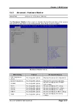
Page 198: ...se CPU Temperature Tcase No changeable options Displays the processor s temperature System Temperature No changeable options Displays the system s temperature VCORE No changeable options Detects and d...

Page 199: ...gger a system reset via the 255 level watchdog timer F81866 Watchdog Configuration Screen BIOS Setting Options Description Purpose Enable Watchdog Enabled Disabled Enables Disables F81866 Watchdog tim...

Page 200: ...ation provides advanced CPU settings and some information about CPU CPU Configuration Screen BIOS Setting Options Description Purpose Socket 0 CPU Information Sub Menu Reports CPU Information CPU Spee...

Page 201: ...ngeable options Reports the CPU Microcode Patch Version Max CPU Speed No changeable options Reports the maximum CPU Speed Min CPU Speed No changeable options Reports the minimum CPU Speed Processor Co...

Page 202: ...le options Reports if Intel VT x Technology is supported by the processor VMM can utilize the additional hardware capabilities provided by Vanderpool Technology Previously codenamed Vanderpool VT x re...

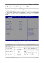
Page 203: ...functions available when the SATA hard drive is set to work in AHCI mode IDE Configuration Screen AHCI Mode BIOS Setting Options Description Purpose SATA Controller s Disabled Enabled Enables or Disab...

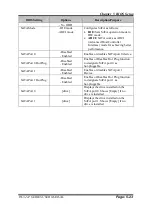
Page 204: ...r disables SATA port 0 device SATA Port 0 HotPlug Disabled Enabled Enables or Disables Hot Plug function to designate SATA port 0 as hot pluggable SATA Port 1 Disabled Enabled Enables or disables SATA...

Page 205: ...8 Advanced OS Selection Menu Path Advanced OS Selection The OS Selection allows users to select the operating system from Windows 7 or Windows 8 x 10 OS Selection Screen BIOS Setting Options Descripti...

Page 206: ...reen BIOS Setting Options Description Purpose CSM Support Disabled Enabled Disables or Enables CSM support CSM16 Module Version No changeable options Displays the current CSM Compatibility Support Mod...

Page 207: ...devices system can boot Network Do not launch Legacy Controls the execution of UEFI or Legacy PXE Storage Do not launch UEFI Legacy Controls the execution of UEFI or Legacy Storage Video Do not launc...

Page 208: ...s No changeable options Displays number of available USB devices Legacy USB Support Disabled Enabled Auto Enables support for legacy USB XHCI Hand off Disabled Enabled This is a workaround for OSes w...

Page 209: ...re it properly reports itself to the Host Controller Auto uses default value for a Root port it is 100 ms for a Hub port the delay is taken from Hub descriptor Device power up delay in seconds multipl...

Page 210: ...orth Bridge The North Bridge allows users to configure LCD control settings and displays the DRAM information on the platform North Bridge Screen BIOS Setting Options Description Purpose LCD Control S...

Page 211: ...North Bridge LCD Control The LCD Control allows users to select the primary and secondary display device LCD Control Screen BIOS Setting Options Description Purpose Primary IGFX Boot Display CRT LVDS...

Page 212: ...ing Options Description Purpose Restore AC Power Loss Power Off Power On Last State Selects AC power state when the power is re applied following a power failure Power Off keeps the system powered off...

Page 213: ...s from changing your BIOS settings You can configure an Administrator password and then configure a user password An administrator has much more privileges over the settings in the Setup utility than...

Page 214: ...e boot order from the available bootable device s and Hardrive BBS option priorities Boot Screen BIOS Setting Options Description Purpose Setup Prompt Timeout Numeric from 1 to 65535 Number of seconds...

Page 215: ...llow user to select boot order of available drive s 5 7 1 Boot Hard Drive BBS Priorities Menu Path Boot Hard Drive BBS Priorities Select Hard Drive BBS Priorities from the Boot menu to configure the b...

Page 216: ...system Select Save Changes and Reset to validate the changed BIOS settings and then restart the system Discard Changed BIOS Settings To cancel the BIOS settings you have previously configured select...

Page 217: ...No changeable options Resets without saving any changes made in BIOS settings Save Changes No changeable options Save Changes done so far to any of the setup options Discard Changes No changeable opt...

Page 218: ...stem as well as the part numbers of the PA 3222 system Exploded Diagram for System Top Case Exploded Diagram for System Exploded Diagrams for System LCD Panel Exploded Diagram for HDD Exploded Diagram...

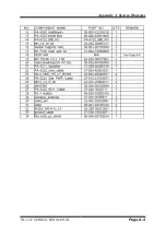
Page 219: ..._B PA 3222_TOP Unit M6 Stand Rubber Foot S1608 mini_pcie_door Black PA 3100 Side DOOR Black PA 3100_Printer_Unit PS 3100 I O Cable Cover Black Lens HHP 4F PART NO Q TY REMARK 1 N A 1 See Page A 3 2 N...

Page 220: ...Appendix A System Diagrams PA 3222 SERIES USER MANUAL Page A 3 System Exploded Diagram 27 33 28 15 24 17 22 19 15 14 18 29 25 20 23 16 26 30 13 31 34 21 12...

Page 221: ...Appendix A System Diagrams PA 3222 SERIES USER MANUAL Page A 4...

Page 222: ...Appendix A System Diagrams PA 3222 SERIES USER MANUAL Page A 5 Exploded Diagrams For System LCD Panel With MSR and RFID Modules 60 59 62 61 80 63 64 65 73 66 83 72 73 67 82 74 76 68 81 69 71 77 70...

Page 223: ...4 04100165 1 119 led_3mm_green 27 018 40008071 1 120 Canoe Clip MB 1A 30 076 04200000 1 121 PA 3222_I button_cable xxx xxxxxxxxxx 1 122 PA 3222_LCDS_Cable 27 020 40005111 1 123 PA 3122_Touch_cable 27...

Page 224: ...System Diagrams PA 3222 SERIES USER MANUAL Page A 7 Exploded Diagrams For System LCD Panel With MSR and i Button Modules 110 111 134 121 113 112 115 114 116 133 123 124 117 132 119 118 131 127 122 12...

Page 225: ...S USER MANUAL Page A 8 Exploded Diagram For HDD 137 138 136 135 NO COMPONENT NAME PART NO Q TY REMARK 135 2inch_SATA_HDD See Order 1 136 PA 3222 HDD Holder 80 029 03001400 2 137 Sata Cable 27 012 3390...

Page 226: ...ERIES USER MANUAL Page A 9 Exploded Diagram For MSR Module 142 141 139 140 NO COMPONENT NAME PART NO REMARK 139 ps3100_msr_holder sldprt 20 029 03005165 1 140 MSR See Order 1 141 M3_L6_F_B 22 215 3006...

Page 227: ...Appendix A System Diagrams PA 3222 SERIES USER MANUAL Page A 10 Exploded Diagram For Fingerprint Module 150 149 147 148...

Page 228: ...0 31300165 1 154 SII 3 Thermal Printer Base Slide 52 701 05017003 1 155 M2_L4_I_Ni 22 272 20004011 4 156 EMI_GASKET_20X5x0 5 90 050 31200165 1 157 ps3100_paper_cover_Unit N A 1 See Next Page 158 M3_L5...

Page 229: ...2110165 1 168 T2_L8_R_B 22 125 20008011 2 169 ps3100_paper_cover_v2 30 002 02530165 1 170 include_holder 20 029 03006165 1 171 ps3100_printer_cover_ejector 30 002 09210165 1 172 ps3100 spring for_ejec...

Page 230: ...5 1 182 SII 2 Thermal Printer Base Side EMI_GASKET_20X5x0 5 52 701 01020003 1 183 90 050 31200165 1 184 M2_L4_I_Ni 22 272 20004011 3 185 ps3100_paper_cover_Unit N A 1 See Next Page 186 M3_L5_W_Ni 22 2...

Page 231: ...65 1 197 T2_L8_R_B 22 125 20008011 2 198 ps3100_paper_cover_v2 30 002 02530165 1 199 include_holder 20 029 03006165 1 200 ps3100_printer_cover_ejector 30 002 09210165 1 201 ps3100 spring for_ejector 2...

Page 232: ...Appendix A System Diagrams PA 3222 SERIES USER MANUAL Page A 15 With Paper Holder Without Paper Holder 03...

Page 233: ...ed Diagram For VFD Module 208 209 211 210 212 NO COMPONENT NAME PART NO Q TY REMARK 208 ps3100_vfd_cover 30 002 28114165 1 209 ps3100_vfd_window 30 002 02230165 1 210 VFD_Model MB 4103RA 11N 1 211 POR...

Page 234: ...B Technical Summary This appendix will give you a brief introduction of the allocation maps for the system resources The following topics are included Interrupt Map DMA Channels Map I O Map Memory Map...

Page 235: ...R Pentium R Processor PCI Express Root Port 4 0F4E IRQ 19 Intel R Atom TM Celeron R Pentium R Processor AHCI 0F23 IRQ 22 High Definition Audio Controller IRQ 81 Microsoft ACPI Compliant System IRQ 82...

Page 236: ...IRQ 117 Microsoft ACPI Compliant System IRQ 118 Microsoft ACPI Compliant System IRQ 119 Microsoft ACPI Compliant System IRQ 120 Microsoft ACPI Compliant System IRQ 121 Microsoft ACPI Compliant System...

Page 237: ...IRQ 158 Microsoft ACPI Compliant System IRQ 159 Microsoft ACPI Compliant System IRQ 160 Microsoft ACPI Compliant System IRQ 161 Microsoft ACPI Compliant System IRQ 162 Microsoft ACPI Compliant System...

Page 238: ...ompliant System IRQ 188 Microsoft ACPI Compliant System IRQ 189 Microsoft ACPI Compliant System IRQ 190 Microsoft ACPI Compliant System IRQ 4294967292 Realtek PCIe GBE Family Controller IRQ 4294967293...

Page 239: ...064 0x00000064 Standard PS 2 Keyboard 0x00000065 0x00000065 Motherboard resources 0x00000067 0x00000067 Motherboard resources 0x00000070 0x00000077 System CMOS real time clock 0x00000070 0x00000077 Mo...

Page 240: ...ard resources 0x00000D00 0x0000FFFF PCI bus 0x0000E000 0x0000EFFF Intel R Atom TM Celeron R Pentium R Processor PCI Express Root Port 4 0F4E 0x0000E000 0x0000EFFF Realtek PCIe GBE Family Controller 0x...

Page 241: ...mily Controller 0xD0700000 0xD070FFFF Intel R USB 3 0 eXtensible Host Controller 0xE0000000 0xEFFFFFFF Motherboard resources 0xFED01000 0xFED01FFF Motherboard resources 0xFED03000 0xFED03FFF Motherboa...

Page 242: ...ssor MBI Device 33BD 0xD0716000 0xD07167FF Intel R Atom TM Celeron R Pentium R Processor AHCI 0F23 0xD0000000 0xD03FFFFF Intel R Atom TM Processor E3800 Series Intel R Celeron R Processor N2920 J1900...

Page 243: ...re the configuration registers The chip selects the Logical Device and activates the desired Logical Devices through Extended Function Index Register EFIR and Extended Function Data Register EFDR The...

Page 244: ...extended function mode mov dx 2eh mov al 87h out dx al out dx al Select Logical Device 7 of watchdog timer mov al 07h out dx al inc dx mov al 07h out dx al Enable Watch dog feature mov al 030h out dx...

Page 245: ...222 SERIES USER MANUAL Page B 12 in al dx and al 30h out dx al Set timeout interval as 30seconds and start counting dec dx mov al 0F6h out dx al inc dx mov al 1Eh out dx al Exit the extended function...

Page 246: ...py AMI flash utility AFUDOS exe v5 07 01 into the storage device 4 Make sure the target system can first boot to the bootable device 1 Connect the bootable USB device 2 Turn on the computer and press...

Page 247: ...Appendix B Technical Summary PA 3222 SERIES USER MANUAL Page B 14...

Page 248: ...X Don t check ROM ID III BIOS Update Procedure 1 Use the bootable USB storage to boot up the system into the DOS command prompt 2 Type AFUDOS 6722xxxx bin p b n x and press enter to start the flash pr...

Page 249: ...MANUAL Page B 16 5 Restart the system and boot up with the new BIOS configurations 6 The BIOS Update is completed after the system is restarted 7 Reboot the system and verify if the BIOS version show...

Reviews: