


Reference
MVI56-PDPMV1 ♦ ControlLogix Platform
User Manual
PROFIBUS DPV1 Master
Page 238 of 251
ProSoft Technology, Inc.
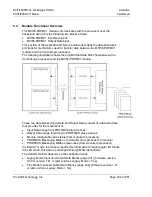
5.4.2 Flex Mode Input and Output Data Blocks
The following illustration shows how the transfer of data, mailbox block, and
status data is performed between the MVI56-PDPMV1 and the ControlLogix
processor.
The PROFIBUS I/O data is transferred through the backplane I/O images. The
status and mailbox data is transferred through MSG instructions.
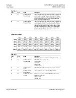
Block ID Numbers for Transfer
Block
Type
Description
0
Input Data
This block is generated only if the module has a single input block
(the configured PROFIBUS input data fits into one input backplane
block). It allows the switching between two blocks with different
block IDs but with same content. So in fact block 0 and block 1 will
transfer the same PROFIBUS input data.
1 to
n
Input Data
Input data from PROFIBUS network with each block containing up
to 242 words of data (refer to Input Data Block Format (Input
Image) (Local:1:I.Data Controller Tag) (page 239))
1 to
n
Output Data
Output data for PROFIBUS network with each block containing up
to 243 words of data (refer to Output Data Block Format (Output
Image) (page 244))
Note: T
he maximum block count
n
will depend on the configured PROFIBUS I/O size and the
backplane block size for each application. For example, if the PROFIBUS input = 100 and each
backplane block will transfer 20 words of PROFIBUS data, then
n
=5.


