


Reference MVI56-DEM
♦
ControlLogix Platform
Honeywell DE Communication Module
ProSoft Technology, Inc.
Page 55 of 80
March 6, 2008
5.5.1 Installation
Instructions
1
Power, input and output wiring must be in accordance with Class I, Division 2
wiring methods [Article 501-4(b) of the National Electrical Code, NFPA 70]
and in accordance with the authority having jurisdiction. The following
warnings must also be heeded:
2
Warning - Explosion Hazard - Substitution of components may impair
suitability for Class I, Division 2
3
Warning - Explosion Hazard - When in hazardous locations, turn off power
before replacing or wiring modules
4
Warning - Explosion Hazard - Do not disconnect equipment unless power has
been switched off or the area is known to be non-hazardous.
5.5.2 DEM Board Power Cabling
The DEM module is receives its power from the backplane. However, the DEM
board receives its power externally. The power cabling setup is as follows:
+
-
24 VDC
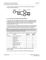
5.5.3 Non-Redundant Configurations
In a typical Non-Redundant configuration, a single FTA is connected to a single
module. The FTA available in this configurations is:
Honeywell FTA Model
Description
Size
MU-TSTX03
Compression Terminals
15.24 x 12.065 cm
Note: This unit is provided by ProSoft Technology
This unit is shipped standard with each MVI56-DEM unit, along with a 3-meter
cable. If other configurations are required, please contact ProSoft Technology.
5.5.4 Redundant
Configurations
The DE I/O system supports the implementation of redundancy at the I/O level
quite easily. Using a standard Redundant FTA, a set of instruments can be
connected to two MVI56-DEM modules. These two modules can be in separate
racks or in the same racks, with either one or two PLC processors themselves in
a redundant configuration.
Honeywell FTA Model
Description
Size
MU-TSTX13
Compression Terminals
30.73 x 12.065 cm
MU-TSTX53
Screw Terminals
30.73 x 12.065 cm
Note: These units are available from ProSoft Technology upon request


