PLX51-DL-232
Diagnostics
Data Logger
User Manual
ProSoft Technology, Inc.
Page 39 of 59
4
The
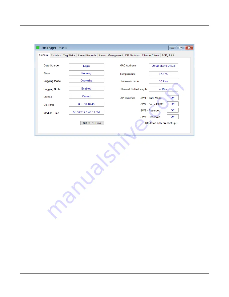
Status
window contains multiple tabs to display the current status of the PLX51-
DL-232.
Figure 5.4 - Status monitoring - General
Page 1: ...PLX51 DL 232 Data Logger Data Storage Module June 22 2022 USER MANUAL...
Page 2: ...ns specifications and dimensions may contain technical inaccuracies or typographical errors ProSoft Technology makes no warranty or representation as to its accuracy and assumes no liability for and r...
Page 3: ...ProSoft Technology Inc Page 3 of 59 Agency Approvals and Certifications Please visit our website www prosoft technology com...
Page 4: ...on Software 13 3 2 Network Parameters 14 3 2 1 DHCP Server Settings 14 3 2 2 Network Settings 16 3 3 Creating a New Project 18 3 4 Configuring the PLX51 DL 232 20 3 4 1 General Tab 20 3 4 2 Serial Tab...
Page 5: ...45 5 2 7 Ethernet Clients Tab 46 5 2 8 TCP ARP Tab 47 5 3 DF1 Packet Capture 48 5 4 Modbus Packet Capture 50 5 5 Module Event Log 53 5 6 Web Server 54 6 Technical Specifications 55 6 1 Dimensions 55...
Page 6: ...trucks drilling rigs or snow plows Once the equipment returns back to its base the historical data can be uploaded and transferred to a more permanent storage device The PLX51 DL 232 can also be conf...
Page 7: ...ode Hold Figure 1 2 Memory Schematic The PLX51 DL 232 is configured using the ProSoft PLX50 Configuration Utility This program can be downloaded from www prosoft technology com free of charge The PLX5...
Page 8: ...operation Table 1 2 Additional Information Resource Link PLX50 Configuration Utility Installation www prosoft technology com User Manual Datasheet Example Code UDTs www prosoft technology com Etherne...
Page 9: ...nector positive negative and Earth The RS232 port uses a four way connector Tx Transmit Rx Receive Gnd Ground and Shield earth connection The Ethernet cable must be wired according to industry standar...
Page 10: ...ngs DIP Switch Description DIP 1 Used to force the PLX51 DL 232 into Safe Mode When in Safe Mode the PLX51 DL 232 does not load the application firmware It waits for new firmware to be downloaded This...
Page 11: ...DIN rail clip to mount onto a 35mm DIN rail Figure 2 3 DIN rail specification The DIN rail clip is mounted on the bottom of the PLX51 DL 232 Use a flat screw driver to pull the clip downward Once the...
Page 12: ...ld of the RS232 port is internally connected to the power connector earth Thus when using a shield it is important to connect the Earth terminal on the power connector to a clean earth Failing to do t...
Page 13: ...gy Inc Page 13 of 59 3 Setup 3 1 Install Configuration Software The PLX51 DL 232 is configured using the PLX50 Configuration Utility environment This software can be downloaded from www prosoft techno...
Page 14: ...DL 232 with the required network parameters IP address subnet mask etc There are a number of DHCP utilities available However it is recommended to use the DHCP server in the PLX50 Configuration Utili...
Page 15: ...ddress dialog box opens Figure 3 4 Assigning IP Address The required IP address can then be either entered or a recently used IP address can be selected by clicking on an item in the Recent list If th...
Page 16: ...g to a DHCP mode after the power is cycled again In addition to the setting the IP address other network parameters can be set during the DHCP process These settings can be viewed and edited by clicki...
Page 17: ...ntext menu including the Port Configuration option Figure 3 8 Selecting Port Configuration 4 All relevant Ethernet port configuration parameters can be modified using the Port Configuration dialog box...
Page 18: ...t Before you configure the PLX51 DL 232 a new PLX50 Configuration Utility project must be created 1 Click on File New Figure 3 10 Creating a new project 2 A new project is created and displayed in the...
Page 19: ...on Figure 3 12 Selecting a new PLX51 DL 232 5 The device appears in the Project Explorer tree and its configuration window is opened The device configuration window can also be opened by double clicki...
Page 20: ...nfiguration window is opened by either double clicking on the PLX51 DL 232 icon in the tree or right clicking the PLX51 DL 232 icon and selecting Configuration Figure 3 14 General Configuration Data L...
Page 21: ...ific parameters For Modbus RTU only the Baud Rate and Parity need be configured Table 3 2 Serial ModbusRTU and DF1 configuration parameters Parameter Description Baud Rate This configures the speed of...
Page 22: ...Source ControlLogix and Compact Logix controllers DF1 Source For collecting data over DF1 Serial communications Modbus Source for ModbusRTU Serial and ModbusTCP Ethernet communications Once the data...
Page 23: ...he Logix Source tab is used to configure tags from Rockwell Automation Logix controllers over EtherNet IP The PLX51 DL 232 can read tags from up to three separate controllers A Target Name must be pro...
Page 24: ...omatically scans for all available EtherNet IP devices Figure 3 18 Target Browser Window 7 If the Ethernet IP module is a bridge module it can be expanded by right clicking on the PLX51 DL 232 icon an...
Page 25: ...er associated with each controller Figure 3 20 Logix Tag configuration Important Tag names need to match in order for the PLX51 DL 232 to correctly identify the tag Full tag names are needed for tags...
Page 26: ...o display the DELETE option Figure 3 22 Deleting Tags 3 5 3 DF1 Source A maximum of three DF1 Sources can be configured The configuration of each source requires a Device Name used as a reference for...
Page 27: ...TCP IP only and a Node Address Fig 3 24 Modbus Source Configuration 3 6 Module Download Once the configuration is complete it must be downloaded to the PLX51 DL 232 Before downloading the connection...
Page 28: ...an be entered manually or selected by means of the Target Browser Figure 3 26 Connection Path 3 To initiate the download right click on the PLX51 DL 232 icon and select Download Figure 3 27 Connection...
Page 29: ...greater than 30 seconds you will be prompted to set the PLX51 DL 232 time to that of the PC time Figure 3 29 Setting module time 6 The PLX51 DL 232 time is used only for the event log Within the PLX50...
Page 30: ...hernet module 1 Right click on the Ethernet Bridge in RSLogix 5000 and select New Module Then select ETHERNET MODULE and click Ok Figure 4 1 Add a Generic Ethernet Module in RSLogix 5000 2 Enter the I...
Page 31: ...which the input and output assemblies are exchanged The recommended value is 500 ms Refer to the technical specification section in this document for further details on the limits of the RPI Importan...
Page 32: ...he User Defined sub folder in the Data Types folder and selecting Import Data Type The assemblies are then assigned to the UDTs with a ladder copy instruction COP Figure 4 4 RSLogix 5000 I O module tr...
Page 33: ...ology Inc Page 33 of 59 2 Select the proper L5X file Figure 4 6 Selecting partial import file The import creates the following The required UDTs user defined data types Controller tags representing th...
Page 34: ...d to change the routine to map to the correct PLX51 DL 232 instance name Make sure that the mapping routine is called by the Program s Main Routine Figure 4 7 Imported RSLogix 5000 objects Refer to th...
Page 35: ...the PLX51 DL 232 that was configured under the General Configuration tab in the PLX50 Configuration Utility Status Running BOOL Set if the PLX51 DL 232 has a valid configuration and is reading tags St...
Page 36: ...ption DataSource ModbusRTU BOOL Set if the data source is set to Modbus RTU DataSource ModbusTCP BOOL Set if the data source is set to Modbus TCP IP DataSourceReadCount DINT The number of tag reads fr...
Page 37: ...X51 DL 232 has booted and is running correctly If the LED is red then the PLX51 DL 232 is not operating correctly For example if the PLX51 DL 232 application firmware has been corrupted or there is a...
Page 38: ...status in the PLX50 Configuration Utility the PLX51 DL 232 must be online If the PLX51 DL 232 is not Online following a recent configuration download right click on the PLX51 DL 232 icon and select th...
Page 39: ...232 Diagnostics Data Logger User Manual ProSoft Technology Inc Page 39 of 59 4 The Status window contains multiple tabs to display the current status of the PLX51 DL 232 Figure 5 4 Status monitoring...
Page 40: ...t In this state the event index has rolled over at least once Inhibited The module has stopped reading and logging data because the user has inhibited it from Logix Stopped The module has stopped logg...
Page 41: ...eads The number of tag reads from the configured data source Log Index The current record index being written to Unload Index The upload record index Managed by the Unload Service Table 5 4 Logix stat...
Page 42: ...igure 5 6 Tag Status Table 5 5 Tag Status Statistic Description TagID Configured Tag ID for the specific Tag Register File Device The configured source device where the tag is extracted Tagname The Ta...
Page 43: ...ime stamp and value Figure 5 7 Recent Records Table 5 6 Recent Records Statistic Description Index Logged data index Date Time The time stamp when the data was logged Tag ID Configured Tag ID for the...
Page 44: ...csv file format Options to reset the log indices and erasing the cache are also available Figure 5 8 Record Management Table 5 7 Record Management Parameter Description Upload All Records to CSV Uplo...
Page 45: ...nection has timed out Class 1 Forward Open Count Number of Class 1 Connection establish attempts Class 1 Forward Close Count Number of Class 1 Connection close attempts Class 1 Connection Count Number...
Page 46: ...onnection Counts Table 5 9 CIP Statistics Statistic Description ARP Clients Number of active clients in the ARP table TCP Clients Number of active connections in the TCP client table EtherNet IP Clien...
Page 47: ...Remote Port number and Local Port number Figure 5 11 TCP and ARP Table Entries Table 5 11 ARP Table Statistic Description MAC Address MAC address of the client in the ARP Table IP Address IP address...
Page 48: ...1 DL 232 double click on the DF1 Packet Capture selection in the Project Explorer tree Figure 5 12 Selecting DF1 Packet Capture 2 The DF1 Packet Capture window opens and automatically starts capturing...
Page 49: ...The status of the packet Received packets are checked for valid DF1 constructs and valid checksums Dirn The direction of the packet either transmitted Tx or received Rx Src DF1 node address of the mes...
Page 50: ...Capture Viewer option in the Tools menu Figure 5 15 Selecting the DF1 Packet Capture Viewer 5 4 Modbus Packet Capture The PLX51 DL 232 provides the capability to capture the Modbus traffic for analys...
Page 51: ...9 2 The Modbus Packet Capture window opens and automatically starts capturing all Modbus packets Figure 5 17 Modbus packet capture 3 To display the captured Modbus packets the capture process must fir...
Page 52: ...for valid Modbus constructs and valid checksums Dirn The direction of the packet either transmitted Tx or received Rx Node Modbus node address of the message destination Description A brief descriptio...
Page 53: ...select the Event Viewer option in the Project Explorer tree Figure 5 20 Selecting the PLX51 DL 232 Event Log 6 The Event Log window opens and automatically reads all the events from the PLX51 DL 232 7...
Page 54: ...ou to view various diagnostics of the PLX51 DL 232 without the PLX50 Configuration Utility or RSLogix 5000 This includes Ethernet parameters system event log advanced diagnostics and application diagn...
Page 55: ...Manual ProSoft Technology Inc Page 55 of 59 6 Technical Specifications 6 1 Dimensions Below are the PLX51 DL 232 enclosure and DIN rail dimensions All dimensions are in millimeters Figure 6 1 Module E...
Page 56: ...NEMA UL Open Type Temperature 20 to 70 C Earth connection Yes terminal based Emissions IEC61000 6 4 ESD Immunity EN 61000 4 2 Radiated RF Immunity IEC 61000 4 3 EFT B Immunity EFT IEC 61000 4 4 Surge...
Page 57: ...a Types Supported BOOL SINT INT DINT or REAL Cached Records Non Volatile Yes Log triggers supported Yes Data Sources Logix Tags DF1 Files Modbus RTU and TCP IP registers 6 5 Serial Port Table 6 4 Seri...
Page 58: ...Inc Page 58 of 59 6 7 Modbus Table 6 6 Modbus specification Specification Rating Supported Ports Modbus RTU Modbus TCP IP Functions Supported Read Coils Function Code 1 Read Discrete Inputs Function...
Page 59: ...rica Corporate Location Europe Middle East Africa Regional Office Phone 1 661 716 5100 info prosoft technology com Languages spoken English Spanish REGIONAL TECH SUPPORT support prosoft technology com...