background image

16

8

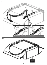
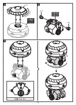
Left View

左視圖

右視圖

Right View

Top View

俯視圖

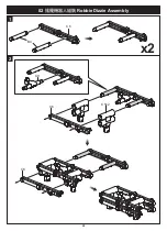
GEAR BOX

齒輪箱模組

MODULE

C7

Click

咔噠

Click

咔噠

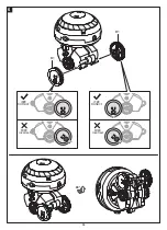
B3x2

Correct 

 Incorrect

正確

錯誤

Correct 

 Incorrect

正確

錯誤

Correct 

 Incorrect

正確

錯誤

Summary of Contents for GE-635

Page 1: ...GE 635 Manual Assembly Instruction...

Page 2: ...bly Base Module Assembly Arm Left Module Assembly Arm Right Module Assembly 1 1 1 2 4 4 4 4 5 5 5 6 Gear Box Module Assembly 13 Track Module Assembly 17 01 Mech Mushroom Assembly 24 How to Play 26 02...

Page 3: ...and secure the little guy finishing a long track in the 3D world you will not only have a lot of fun challenging your techniques but also learning the gyroscopic basic physics such as rotation preces...

Page 4: ...NLY the parts as instructed but not others Cut the plastic parts when they are required Do not cut them in advance A Red B White P11 P12 P13 P14 P15 P8 1 pc Hex Shaft P9 1 pc Round Shaft Short Round S...

Page 5: ...not trim off the protrusion belonged to original plastic parts All features of parts should be kept completely Read It Before Assembly Must know Please read through and follow the tips below before a...

Page 6: ...Rip Cord Assembly Root Module Assembly Leg Left Module Assembly Leg Right Module Assembly Rip Cord ROOT MODULE Cut off the burrs before assembly LEG MODULE L LEG MODULE R A15 B8 B15 B7 B13 B11 P9 B16...

Page 7: ...5 Arm Right Module Assembly Arm Left Module Assembly B9 B6 B12 B6 B18 B18 B12 B2 A17 C17 A17 Cut off the burrs before assembly burr burr Base Module Assembly P6x3 C19 BASE MODULE ARM MODULE L R ARM MO...

Page 8: ...6 1 How to Oil The Parts P2 Core Module Assembly 1 1 C21 P11 Tissue Paper P15 Note Oil the parts when appears Example Do not oil outside the shadow as shown below Apply Oil Cup Cotton Swab Round Shaft...

Page 9: ...4 7 2 3 C11 C11 C13 A5 P1 C12 A12 A14 P6x3 P14 x4 3 1 1 1 1 3 3 3 3 3 3 2 2 2 2 2 2 2 2 P14 Sponge P13x2 2 1 Incorrect This side faces up Correct Incorrect...

Page 10: ...5 6 7 8 180 P1 A2 A1 P5 B14 1 2 1 3 2 2 Correct Incorrect Round Shaft...

Page 11: ...9 8 9 180 P2 P2 TOP TOP BOTTOM BOTTOM P6x3 The gap lengths of the both sides should be the same Correct Incorrect Correct Incorrect 1 1 CORE MODULE...

Page 12: ...ore Rotor Functional Testing Warning Do not pull the rip cord when P2 is exposed P2 Press down the body to make both sides of gap equal length P2 P2 P2 90 90 lock it up lock it up Correct Incorrect CO...

Page 13: ...3 2 11 90 Rip Cord Insert the rip cord as illustration shown Face the teeth side towards the mark besides the entrance ROOT MODULE Correct Incorrect l lo oc ck k i it t u up p...

Page 14: ...12 Keep pulling to speed up Put the metal rod into the hole on Body to stop the rotor from running Do not touch the teeth side when pulling Stop the Testing Rip Cord Rip Cord...

Page 15: ...2 3 13 1 C22 C16 P2 P2 P8 P4x3 P10 A6 P7 P10 Gear Box Module Assembly 1 1 1 1 Gear with Shaft A Gear with Shaft A Gear with Shaft B 1 2 3 Correct Incorrect...

Page 16: ...14 5 4 take out C20 P3 C10 Cut off the burrs before assembly Cut off the burrs before assembly A7 C10 P4 Green P4 Green P4 Green P2 White P3 Red P12 A8 C10 C10 Correct Incorrect Gear with Shaft B...

Page 17: ...15 6 7 90 90 For better understanding of how C8 is assembled the finished Step 5 is omitted in the illustration C8 C8 P6x2 A3...

Page 18: ...16 8 Left View Right View Top View GEAR BOX MODULE C7 Click Click B3x2 Correct Incorrect Correct Incorrect Correct Incorrect...

Page 19: ...17 1 Color Box Tape Tape 1 1 2 Track Module Assembly Fold the corners inwards along the dotted line...

Page 20: ...2 18 1 1 2 180 Fold the corners inwards along the dotted line Tape Tape...

Page 21: ...19 3 4 x4 x4 1 1 1 1 3 3 2 2 2 2 2 2 2 2 P14 Sponge 1 1 1 1 3 3 2 2 2 2 2 2 P14 Sponge P14 2 P14 1 A11 A9...

Page 22: ...x4 5 20 2 Try your best to prevent the ends from puckering up Avoid the height difference around the overlap if possible 1 1 2 2 2 1 1 F2 Correct Incorrect Correct Incorrect...

Page 23: ...21 x4 6 F1 F1 F2 F2 F1 F1 F1 F2 F2 Please paste F1 to the outer side of F2 Please paste F1 to the outer side of F2 F1 F2 F1 F2 F1 F2 F2 F1 Correct Incorrect Correct Incorrect...

Page 24: ...22 180 F2 F1 F2 F1 F2 F1 Correct Incorrect Please paste F1 to the outer side of F2 F1 F2...

Page 25: ...23 7 TRACK MODULE F2 F1 F1 F1 F2 F2 Correct Incorrect Please paste F1 to the outer side of F2 F1 F2...

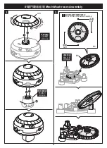
Page 26: ...24 1 2 B5 Cut off the burrs before assembly burr burr B5 1 2 A13 1 1 01 Mech Mushroom Assembly 1 1 2 l it u 2 2 CORE MODULE ROOT MODULE BASE MODULE l lo oc ck k i it t u up p lock it u p...

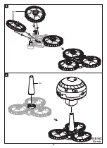
Page 27: ...3 4 25 1 2 2 1 B5 A4 Finish...

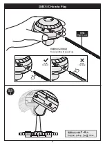
Page 28: ...26 How to Play PLAY 1 Keep pulling to speed up Suggest pulling times 1 5 1 5 Rip Cord Correct Incorrect...

Page 29: ...27 3 Rope Rope 1 5mm PLAY PLAY 2 Suggest pulling times 1 5 1 5 Suggest pulling times 1 5 1 5...

Page 30: ...28 1 2 C6 C9 C5x2 C6 C6 B4 02 Robbie Dizzie Assembly x2...

Page 31: ...29 3 4 5 1 1 A13 2 1 1 A16 A16 lock it u 2 2 lock it u p CORE MODULE GEAR BOX MODULE Side View Lock it up...

Page 32: ...30 6 90 B1 B1 Correct Incorrect Correct Incorrect...

Page 33: ...31 7 8 C1 C2...

Page 34: ...32 9 10 C18x2 C3 B5 B5x2 B5 Finish...

Page 35: ...to Play Keep pulling to speed up Please hold the core module as shown in the illustration Pull the rip cord times to make it march on the spot 10 3 10 Pull the rip cord times to make it go forward 3 R...

Page 36: ...34 1 2 3 1 1 x2 C18 C9 C14 C15 C1 A13 C18 C4 03 Scooter Rider Assembly E2 B10 B17 E1 2 2 lock it u p CORE MODULE...

Page 37: ...4 5 35 90 C2 GEAR BOX MODULE Side View...

Page 38: ...36 6 7 180 ARM MODULE L ARM MODULE R...

Page 39: ...e module as shown in the illustration Keep the head balanced when placing the robot on a table or any flat surface Keep pulling to speed up Finish Suggest pulling times 5 10 5 10 Lock it up How to Pla...

Page 40: ...2 3 38 1 1 1 1 1 Please assemble to the correct side as shown above A13 B1x2 C18x2 04 Stilts bot Module Assembly 180 2 lock it up 2 lock it up 2 lock it up 2 l o c k i t up CORE MODULE ROOT MODULE...

Page 41: ...5 4 39 90 A10 A10 C6 C6 LEG LEG MODULE R LEG MODULE L Finish...

Page 42: ...40 How to Play Keep pulling to speed up Please hold the core moudle as shown in the illustration Suggest pulling times 5 10 5 10 Rip Cord...

Page 43: ...41 B5 B5 Cut off the burrs before assembly burr burr 1 2 1 2 B5 1 2 2 1 B5 x2 05 Speedy Rover Module Assembly BASE MODULE...

Page 44: ...42 3 4 CORE MODULE l o c k i t up...

Page 45: ...5 6 43 BASE MODULE lock it up lock it up...

Page 46: ...w to Play Please hold the core module as shown in the illustration Keep pulling to speed up Do not hold the rover on its two sides Front View Correct Incorrect Incorrect Rip Cord Suggest pulling times...

Page 47: ...45 1 2 3 4 90 C18 C18 A10 A16 A16 A10 C4 06 Roboller Coaster Module Assembly A13 1 1 Side View Side View 2 2 CORE MODULE GEAR BOX MODULE LEG MODULE R LEG MODULE L lock it u p...

Page 48: ...5 46 6 1 1 TRACK MODULE 2 lock it up Side View lock it up Finish...

Page 49: ...w to Play 47 Balance the robot on the track Keep the body balanced when placing the robot on the track Do not let it lean forward or back Demonstation Video Rip Cord Keep pulling to speed up Keep pull...

Page 50: ...s not run smoothly please check whether page 35 step is assembled correctly Make sure Track Module on page 20 step to page 23 step is assembled correctly 1 1 6 6 5 5 7 9 9 2 30 B1 5 3 35 5 7 4 20 23 T...

Page 51: ...24T Red Gear 40 10T Green Gear 48 18T White Tapping Screw 5GE 63500P3 5GE 63500P4 5GE 63500P5 5GE 63500P6 5GE 63500P7 Hex Shaft Hex Shaft 5GE 63500P8 5GE 63500P9 Round Shaft Short 5GE 63500P10 Round...

Page 52: ...All rights reserved 2021001 Tel 886 2 2218 3233 Fax 886 2 2218 2722 E mail science mail prokits com tw https science prokits com tw https shop prokits com tw 1 3 0 7 5 5F No 7 Lane 130 Ming Chung Rd...

Reviews: