

2
3
4
5
Part 2 – Attaching the Mount Arms to the Display (continued)
0153-20191021
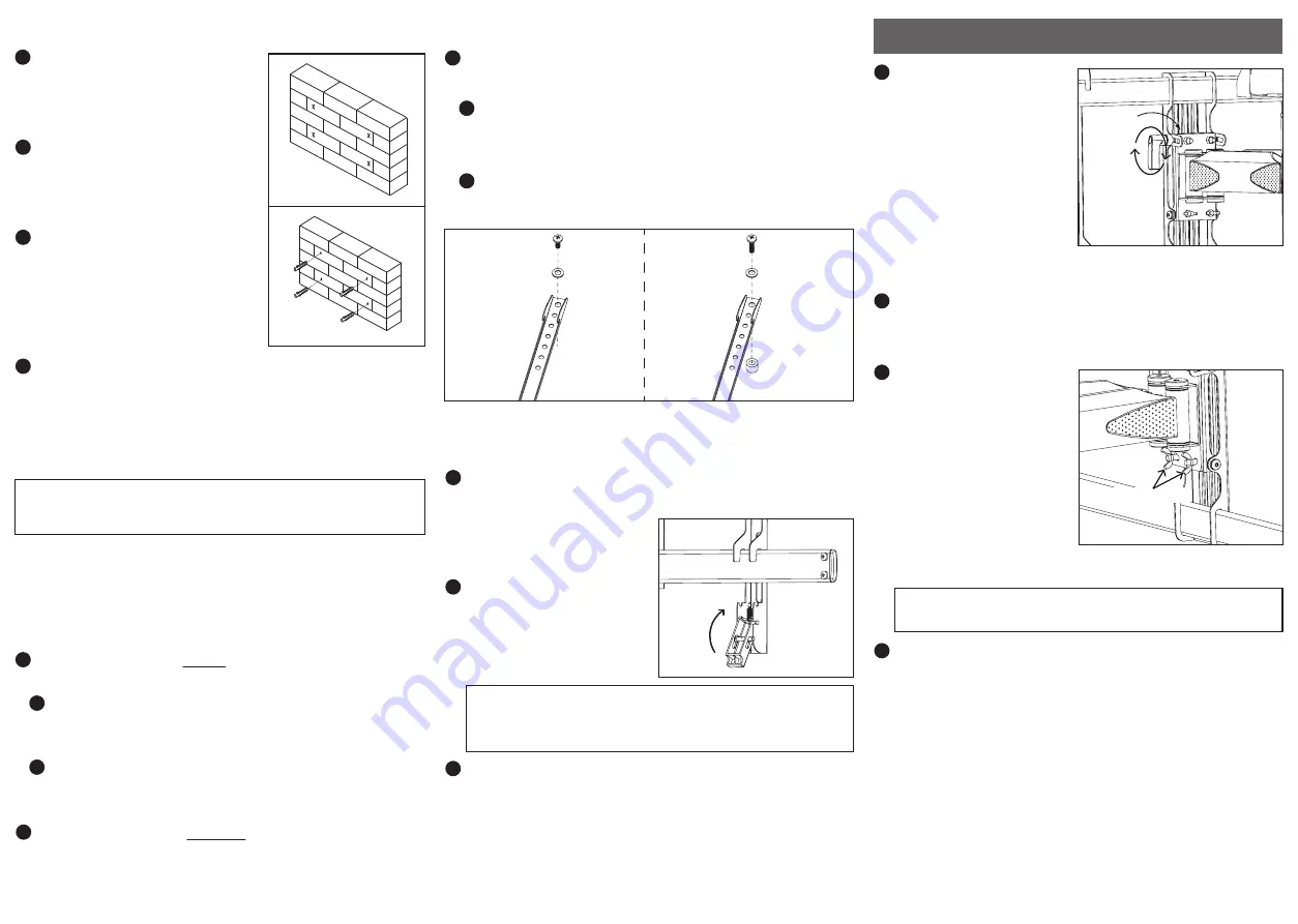
OPERATION AND ADJUSTMENT
A
Fig. 3
Fig. 4
NOTE:
This mount comes with a variety of screw lengths and
diameters to accommodate different display models. Not all of
the hardware in the kit will be used. If you cannot find the
appropriate screw size in the kit provided, consult with the
manufacturer of your display or a professional installer.
Part 2 – Attaching the Mount Arms to the Display
IMPORTANT!
Use extra care during this part of the installation
to avoid damaging your display.
Part 1B – Mounting to the Wall (Concrete) (continued)
While another person holds the
mount in place, mark four
locations for securing the mount
to the wall (see Fig. 3).
Set the mount aside and drill a
3/8” hole at each marked location.
Remove any excess dust from the
holes.
Insert a concrete anchor (C) into
each hole so that it is flush with
the concrete surface (see Fig. 4). A
hammer can be used to lightly tap
the anchors into place if
necessary.
Attach the mount to the wall with the arrow pointing up
using the lag bolts (A) and washers (B) provided (see Fig. 3).
Do not release the mount until all bolts are secure.
Ensure
that the mount remains level.
A
B
Attach the mount arms to the back of your display using
the screws identified in steps 1 and 2
(see Fig. 5):
If you are using the M4 and M5 screws you will need to
use the M5 Washers (F). If you are using M6 and M8
screws, you will need to use the M8 washers (K).
If you are using the longer screws, you may also need to
use spacers (L or M).
If the back of your display is flat and the mounting holes
are flush with the surface, use the shorter screws (D, E G
or H) from the hardware kit.
B
If the back of your display is curved or if additional space
is needed between the display and the mount, use the
longer screws.
2
Determine the correct diameter of screw to use by carefully
trying one of each size (M4, M5, M6 and M8) from the
hardware kit.
Do not force any of the screws – if you feel
resistance stop immediately and try a smaller diameter
screw.
1
Determine the correct length of screw to use by examining
the back of your display:
2
3
IMPORTANT!
The latches must be closed and locked at
all times to prevent the display from being accidentally
knocked from the mount.
IMPORTANT!
Never fully loosen or remove the level
correction nuts.
1
2
3
4
To change the tilt angle of
your display, have one
person hold the display
firmly in place while
another person loosens
the tilt knob (see Fig. 7).
Once loosened, move your
display to the desired
position, and then
re-tighten the knob.
Do
not release the display until the knob is fully tightened.
Swivel adjustments can be made by moving the display
to the desired position. Be careful that fingers or cables do
not get pinched when moving the mount.
Level correction
adjustments can be made
by rotating the display in
the needed direction. If it
is too difficult to turn the
display or if the display
does not stay in position,
adjust the tension of the
two wing nuts located
behind the faceplate.
Adjust the two nuts evenly (see Fig. 8).
1
With the help of another person, carefully lift your display
and place it on the mount.
Do not release the display
until the mount arms have
securely hooked onto the
mount.
Close the safety latch at the
bottom of each arm. Each
latch will automatically lock
when fully closed (see Fig. 6).
Periodically clean your mount with a soft, dry cloth. Inspect
all screws and hardware at regular intervals to ensure that
no connections have become loose over time. Re-tighten
as needed.
Cables can be routed through the channels located on the
bottom of the mount. Make sure none of the cables can be
pinched during operation of the mount.
Part 3 – Final Assembly
3
Fig. 5
For displays
with curved or
recessed backs.
For displays with
flat backs.
Fig. 8
Fig. 6
Fig. 7
Level correction nuts


