
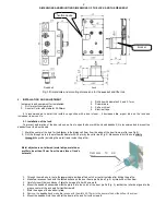
DIMENSIONS AND MOUNTING
Deadbolt
Fig.1. Dimensions and mounting dimensions for the
5. INSTALLATION AND ADJUSTMENT
Instruments and equipment for installation
1. Drill or electric screwdriver.
2. Annular Cutter with diameter 25-26mm.
It is recommended to install the lock
increases its service life.
5.1. Installation of the lock:
To prevent deformation of the door when one tries to open the door with the closed
deadbolt near the door handle.
1. Mark the center of the hole for the blocker
2. Drill the through-hole in the profile with diamet
through the profile (including the metal frame inside the profile)
Metal objects are not allowed (metal chips
profile) closer than 10mm from the end
solenoid.
3. Through the made hole, route the power cable inside profile's notch or route it outside after drilling the profile.
4. Make two recesses flush with the drilled surface on the door frame profile (see Fig. 2)
5. Carefully insert the lock blocker 1 into the hole and fix it with screws
6. Mount the deadbolt assembled with the plate
groove center of the lock and fix it with screws
7. Mark the edges of the deadbolt plate.
8.
Remove the
deadbolt
and make the recess with the width 60
9. Mount the deadbolt into the notch of the door profile
fixation device
2
MOUNTING DIMENSIONS OF THE LOCK AND THE DEADBOLT
Lock
Dimensions and mounting dimensions for the
deadbolt
and the lock.
Instruments and equipment for installation:
26mm.
3. Drill bits with diameter 2.3 and 3.1mm.
4. Screwdrivers.
5. Knife or chisel.
6. Electrical tape.
lock in conjunction with a door closer – it decreases the
To prevent deformation of the door when one tries to open the door with the closed deadbolt, it is recommended to mount the
for the blocker in the distance 29mm from the edge of the door frame
hole in the profile with diameter 25-26 mm by the cutter (see Fig.2). Make sure to drill the hole
(including the metal frame inside the profile).
chips, metal door
end face of lock's
the power cable inside profile's notch or route it outside after drilling the profile.
Make two recesses flush with the drilled surface on the door frame profile (see Fig. 2) by the knife or the chisel.
into the hole and fix it with screws 4.
assembled with the plate 2 into the notch of the door profile (Fig. 3), so that the roller be aligned to the
groove center of the lock and fix it with screws 5.
plate.
and make the recess with the width 60-70mm in the door profile by the knife or the chisel.
into the notch of the door profile and fix it with screws 5.
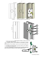
fixation device
Clearance 10 mm
10mm
DEADBOLT
and the lock.
Drill bits with diameter 2.3 and 3.1mm.
it decreases the impact load on the lock and
, it is recommended to mount the
in the distance 29mm from the edge of the door frame profile (see Fig.2).
ig.2). Make sure to drill the hole utterly
the power cable inside profile's notch or route it outside after drilling the profile.
by the knife or the chisel.
into the notch of the door profile (Fig. 3), so that the roller be aligned to the
70mm in the door profile by the knife or the chisel.
blocker