ProMinent TUC 1 Assembly And Operating Instructions Manual Download Page 1

DULCO

®

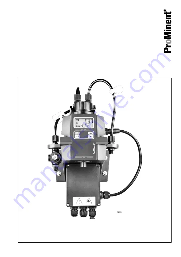
 turb C Measuring Device for Tur‐

bidity
Types: TUC 1, TUC 2, TUC 3, TUC 4

Assembly and operating instructions

EN

Part no. 986062

BA DT 053 08/16 EN

Please carefully read these operating instructions before use. · Do not discard.

The operator shall be liable for any damage caused by installation or operating errors.

The latest version of the operating instructions are available on our homepage.

Mahar Fan

Mahar Fan

Summary of Contents for TUC 1

Page 1: ...tions EN Part no 986062 BA DT 053 08 16 EN Please carefully read these operating instructions before use Do not discard The operator shall be liable for any damage caused by installation or operating...

Page 2: ...correct operation of the unit or is intended to make your work easier Warning information Warning information includes detailed descriptions of the hazardous situation see Chapter 1 1 Labelling of War...

Page 3: ...Symbol Description Display GUI Screen elements e g buttons assignment of function keys CODE Presentation of software elements and or texts Supplemental instructions 3 Mahar Fan Mahar Fan...

Page 4: ...evice Control elements 27 5 2 Overview of operating structure 28 6 Commissioning 31 6 1 Inserting the drying agent 32 6 2 Routine measurement 35 6 3 Access code 36 6 4 Device configuration 37 6 4 1 Se...

Page 5: ...8 1 2 Faults in the process 69 9 Spare parts and accessories 71 10 Disposal of Used Parts 72 11 Declaration of Conformity 73 12 Index 74 Table of contents 5 Mahar Fan Mahar Fan...

Page 6: ...rce of the danger Consequence Fatal or very serious injuries Measure to be taken to avoid this danger Description of hazard Denotes an immediate threat ening danger If the situation is disregarded it...

Page 7: ...sit uation If the situation is disre garded the product or an object in its vicinity could be damaged Type of information Hints on use and additional informa tion Source of the information Additional...

Page 8: ...ired trained in the tasks assigned to him her and possible dangers that could result from improper behaviour as well as having been instructed in the required protective equipment and protective measu...

Page 9: ...ent in which the are employed and know the relevant standards and regulations Electricians must comply with the provisions of the applicable statutory directives on accident prevention Customer Servic...

Page 10: ...Fatal or very serious injuries The unit should only be operated by adequately qualified and tech nically expert personnel Please also observe the oper ating instructions for controllers and fittings a...

Page 11: ...ings Correct measuring and control is only possible if the sensor is working perfectly Check and calibrate the sensor regularly 2 2 Correct and proper use NOTICE Correct and proper use The device is d...

Page 12: ...ndard US EPA 180 1 All device types can be equipped with ultrasonic cleaning TUC 3 TUC 4 or without ultrasonic cleaning TUC 1 TUC 2 The sample cell ultrasonic cleaning system extends the calibration a...

Page 13: ...flow rate Flow rate 6 l h 60 l h Operating tem perature 1 C 50 C Materials that come into con tact with the media Polyamide PA silicone polypropylene PP stainless steel boro silicate glass Power supp...

Page 14: ...i tion system only functions in AUTO oper ating mode The system can detect the following fault states n Incorrect cuvette installed n Error occurred in transducer n Transducer has no contact to the sp...

Page 15: ...box and integrated flow assembly 1 Operating Instructions 1 Drying agent package 1 Cuvette 1 Hose kit n Shut off clamp 1 piece n Back pressure valve 1 piece n Connection hoses with connection pieces f...

Page 16: ...ng Avoid direct sunlight Permissible ambient temperature of the DULCO turb C at installa tion site 1 50 C at max 95 relative air humidity non con densing Consider the permissible ambient temperature a...

Page 17: ...ng site This is the only way to ensure a quick response time from the system Free space above the sensor Leave at least 200 mm clearance above the DULCO turb C for carrying out any work required on th...

Page 18: ...A0515 A B Fig 1 The diagram is not to scale It is for information only All values given in millime tres A Terminal box B DULCO turb C housing Assembly and Installation 18 Mahar Fan Mahar Fan...

Page 19: ...alues given in millime tres A Terminal box B DULCO turb C housing 1 Fasten the terminal box A to the wall with two M4 screws 2 Fasten the DULCO turb C housing B to the wall above the terminal box usin...

Page 20: ...t screw Slight leakage may occur at the bore hole for the vent screw during the installation process This will cease as soon as normal flow is established In the event that the installation con tinues...

Page 21: ...k pressure valve To regulate the flow and in order to remove small air bubbles 2 Vent screw For use on pressurised systems Not used for pressureless systems 3 Hose connector 4 75 mm interior diameter...

Page 22: ...ies Measure Disconnect the power supply before opening the housing Disconnect damaged defective or manipulated devices from the power supply The provision of a suitable iso lating device emergency off...

Page 23: ...mmetrical signal transmission This means that cable lengths of up to 900m can be used The final device on a bus must be equipped with a 120 ohm resistor in order to avoid signal overlapping In order t...

Page 24: ...A0518 Fig 4 Cable assignment for DULCO turb C 1 Sensor cable 2 Liquid tight threaded connection 3 Terminal box Assembly and Installation 24 Mahar Fan Mahar Fan...

Page 25: ...supplied without power cable II Alarm cable threaded connection III Sensor cable threaded connection 1 Terminal Alarm 1 and 2 0 25 1 5 mm2 maximum 2 A 2 Terminal 4 20 mA RS 485 0 25 1 5 mm2 3 Termina...

Page 26: ...Lift off the terminal box cover 3 Remove the blanks from the required bore holes 4 Guide the cables into the threaded connectors 5 Connect the cables with the designated terminals 6 Tighten the clamp...

Page 27: ...ers qualifications on page 8 Fig 6 Overview of device Control elements 1 LCD display 2 UP key 3 DOWN key 4 ENTER button 5 MODE EXIT button Function Description LCD display The parameters of the respec...

Page 28: ...of operating struc ture The sensor is equipped with three modes which can be selected by means of the MODE EXIT button n AUTO mode Standard mode dis play of the current measured values n CAL Calibrat...

Page 29: ...Fig 7 Overview of operating structure Operating diagram 29 Mahar Fan Mahar Fan...

Page 30: ...settings EXTD The procedure for configuring the menu settings is described here Chapter 6 4 Device configuration on page 37 The extended settings are grouped together in order to prevent accidental al...

Page 31: ...asured values above 1000 NTU fall outside the measuring range of this DULCO turb C Measured values above 1100 NTU cause the display to flash and issue a message indicating that the measured value is t...

Page 32: ...g agent needs to be exchanged this is indicated in the lower row of the LCD display Warning DESC for Desiccant drying agent Replacement drying agent bags can be obtained from Prominent or from your lo...

Page 33: ...the new drying agent bag 2 from the packaging and place it together with the humidity indicator card 3 in the lower part of the DULCO turb C 1 In doing so place the humidity indicator card 3 on the n...

Page 34: ...ew drying agent To do this remove the sensor connection cable for 2 seconds from the DULCO turb C and then reconnect it Otherwise the warning DESC may appear on the LCD display A0648 Fig 10 Insert she...

Page 35: ...outine measurement Routine measurement The turbidity can be correctly measured approx 45 60 minutes after beginning measurement commissioning warm up phase When a continuous process water flow is pass...

Page 36: ...e number with the UP or DOWN button and confirm with the ENTER button Entering the access code The access code 333 must be entered in order to access the CAL or CONFIG menus 1 The first number of the...

Page 37: ...the DULCO turb C returns to AUTO mode 6 4 Device configuration 6 4 1 Selecting the output A0530 Fig 12 Selecting the output Function Options Info Output O P n 4 20 mA n 485 n off 4 20 mA Value 4 mA 0...

Page 38: ...ue 20 mA in order to reverse the sign of the output current a lower NTU value can be entered than for value 4 mA in order to reverse the sign of the output current 485 Baud Value baud n 1200 n 2400 n...

Page 39: ...2 00 mA or 0 mA can be selected In the event of an error the configured current value is output to the controller regardless of which measured value is pending If the function is switched off by setti...

Page 40: ...stem error occurs Limit value alarm The turbidity threshold at which the alarm is triggered is referred to as the Limit value alarm You can configure the limit value across the entire display range of...

Page 41: ...n ERROR Select the alarm function Limit value S P 0 1000 NTU Set the Limit value alarm Delay time alarm on DLY 1 30 s Set the number of seconds for the Delay alarm on function Delay time alarm off DLY...

Page 42: ...s as soon as an offset is being used The maximum offset amounts to 1 00 NTU If the device deviation is greater than 1 NTU then it is recommended to carry out a complete calibration A0624 Fig 15 OFFSET...

Page 43: ...e extremely close to each other depending on the accuracy of the reference device then no offset configuration or calibration is required and the procedure can be aborted at this point However if the...

Page 44: ...s completed At this stage the device remains in configuration mode CONFIG Press the key MODE EXIT button in order to return to AUTO 6 4 5 Extended settings Extended settings A0532 Fig 16 Extended sett...

Page 45: ...tings in order to access configura tion for the following options n Speed of response n Screen resolution n LCD illumination bright ness n Units n Ultrasonic cleaning n RS 485 parameters n Alarm dryin...

Page 46: ...id anoma lies caused by air or other influences Select the lowest reaction time i e the lowest number if rapid changes are to be expected which are to be monitored The displayed number is a relative r...

Page 47: ...urb C is able to display a value with up to four digits after the decimal point LCD illumination brightness A0535 Fig 19 LCD illumination brightness Function Options Info LCD illumination brightness B...

Page 48: ...unction Options Info Units UNIT n NTU n FNU Factory setting NTU Select a unit for displaying the turbidity measurement NTU Nephelometric Turbidity Units or FNU Formazin Nephelometric Units Commissioni...

Page 49: ...out an ultrasound transducer then an error message will be shown on the LCD display A0537 Fig 21 Ultrasonic cleaning Function Options Info Ultrasonic cleaning CLN ON On OFF Off Factory setting ON Swit...

Page 50: ...ng 8 The required number of data bits for the communi cations software deployed Parity PRTY nOnE ODD E Factory setting nOnE The parity bit required for the communications soft ware Stop 1 2 Factory se...

Page 51: ...r to activate one or both alarms then you must configure ERROR see Chapter 6 4 3 Configure alarm on page 40 In order to indicate an error via the 4 20 mA signal ERROR ALARM ERLV must be selected in al...

Page 52: ...0 Configure the mA value in order to adapt to the super ordinated control system e g SPC or SCADA One count number corre sponds to 0 01 mA Configuration of 20 mA output Allow a constant output of 20 m...

Page 53: ...the extended settings EXTD to OFF then you can use the button to save the settings and return to the permanent display in AUTO mode see figure Fig 7 If you have set the extended settings EXTD to ON th...

Page 54: ...can exit the configuration menu at any time by pressing the MODE EXIT button In doing so any changes to the parameters that you have modified will be stored Flow controller The flow controller part n...

Page 55: ...00 NTU you must per form calibration with all 3 standard solutions 0 02 NTU 10 0 NTU and 1000 NTU If the sensor is only oper ated in measurement ranges under 10 NTU then you may perform a sim plified...

Page 56: ...ed by the DULCO turb C and use them for control purposes while the signals are being indexed NOTICE Screen resolution For the purposes of indexing we recommend that the DULCO turb C should be set in t...

Page 57: ...tandard solution 10 NTU must be transferred to the cuvette from the storage bottle before it is used for the first time The filling for the 10 NTU cuvette is then usable for 24 hours Do not use the st...

Page 58: ...on afterwards 2 Fill the rinsed cuvette with 20 ml 10 NTU standard solution 3 Clean and dry the exterior of the cuvette before inserting the cuvette into the DULCO turb C 4 The 10 NTU cuvette may now...

Page 59: ...manufacturing tolerances on the calibration process you must index and mark the position on the cuvette with the lowest tur bidity value lowest NTU value You can mark the index points with the help o...

Page 60: ...splayed measured value has stabilised Mark the point on the cuvette with the lowest NTU value with the help of the marking ring supplied so that the marker points towards yourself 6 Remove the 10 NTU...

Page 61: ...to extend the service life of the drying agent The fan is switched on During the calibration countdown After returning to AUTO mode After 5 minutes without input from the operator Whichever occurs fir...

Page 62: ...measured NTU value 2 Open the flow unit by screwing it in a clockwise direction and remove the cuvette sample together with the cuvette 3 Insert the 1000 NTU calibration cuvette into the DULCO turb C...

Page 63: ...ess the key to start calibrating at 1000 NTU A 30 second countdown begins after which the DULCO turb C is calibrated at 1000 NTU A0525 Fig 30 Display Calibration 10 NTU 6 Remove the 1000 NTU calibrati...

Page 64: ...he calibration cuvette 20 from the centre point to the left and then 20 from the centre point to the right Leave the calibration cuvette in the position with the lowest measured value A0524 Fig 31 Dis...

Page 65: ...arker is facing towards you Indexing the standard solution with your cuvette on page 56 12 Slowly rotate the calibration cuvette 20 from the centre point to the left and then 20 from the centre point...

Page 66: ...he in line flow fitting by screwing it in an anticlockwise direction The DULCO turb C is now calibrated and is reset to AUTO mode Incorrect calibration A0528 Fig 34 Display Incorrect calibration If th...

Page 67: ...an error occurs the sensor continues to indicate values however the accuracy of these measured values is uncertain meaning that you cannot rely on the values given For this reason the DULCO turb C di...

Page 68: ...er ally be rectified by the operator This includes for example a lamp failure LAMP or incorrect calibration CAL If an error occurs the sensor continues to indicate values however the accuracy of these...

Page 69: ...omer service 8 1 2 Faults in the process Fault Possible cause Process error Displayed values higher than expected Air bubbles in the sample water Ensure that the outlet bleed valve is open and not blo...

Page 70: ...lower than expected Incorrectly calibrated Calibration see Chapter 7 1 2 Per form calibration on page 61 Upper row of display flashes Sample has exceeded the permissible measurement range Check sampl...

Page 71: ...7877 Cuvette TUC3 TUC4 1037878 Infrared lamp TUC1 TUC3 1037702 White light lamp TUC2 TUC4 1037703 Hose kit 1037879 Pressure regulating valve 1037885 Accessories Accessories Part number Calibration set...

Page 72: ...pply in your country The manufacturer will take back decon taminated used units providing they are covered by adequate postage Decontaminate the unit before returning it for repair To do so remove all...

Page 73: ...ny modification to the product not approved by us will invalidate this declaration Designation of the product Turbidity Sensor DULCOturb C Product type TUC1 TUC2 TUC3 TUC4 Serial number see nameplate...

Page 74: ...ions 6 G General non discriminatory approach 2 I Incorrect calibration 66 L Limit value alarm 40 Links to elements or sections of these instructions or other applicable docu ments 2 Liquid temperature...

Page 75: ...75 Mahar Fan Mahar Fan...

Page 76: ...86062 2 en_GB 2016 ProMinent GmbH Im Schuhmachergewann 5 11 69123 Heidelberg Germany Telephone 49 6221 842 0 Fax 49 6221 842 419 Email info prominent com Internet www prominent com Mahar Fan Mahar Fan...

Reviews: