background image

Only use the original fuses from ProMinent! It is not sufficient

to use a fuse with the above fuse rating.

14.6  Diaphragm rupture sensor

Pin

Allocation

1 (white

4.5 V ... 24 V, max. 10 mA

2 (brown)

OUT, open collector, 24 V, 20 mA

3 (green)

GND

Data

Value Unit

Pulse width (low)*

≥4 ms

* depending on the gear and mains frequency

The polarity is unimportant.

5–25 V DC, in accordance with Namur or DIN 60947-5-6, potential-free

design.

Data

Value Unit

Nominal voltage *

8 VDC

Power consumption - active surface

uncovered

> 3 mA

Power consumption - active surface cov‐

ered

< 1 mA

Rated switching distance

1.5 mm

* Ri ~ 1 kΩ

Cable colour

Polarity

blue

-

brown

+

14.7  Relay

The technical data for the relay are contained in the chapter

"Installation, electrical".

b) Reed switch (identity code specification

"Stroke sensor": 2)

b) Namur sensor (identity code specifica‐

tion "Stroke sensor": 3)

Technical data


69

Summary of Contents for Sigma 2 S2Ca

Page 1: ...ons and the General Operating Instructions for ProMinent motor driven metering pumps and hydraulic accessories Both sets of operating instructions are only valid when read together Original Operating Instructions 2006 42 EC Part no 985894 BA SI 040 05 11 EN Please carefully read these operating instructions before use Do not discard The operator shall be liable for any damage caused by installatio...

Page 2: ...2354454235 1 en_GB 2011 ProMinent Dosiertechnik GmbH Im Schuhmachergewann 5 11 69123 Heidelberg Germany Telephone 49 6221 842 0 Fax 49 6221 842 617 email info prominent com Internet www prominent com 2 ...

Page 3: ...table values 38 8 3 Changing to adjustment mode 38 8 4 Operating mode selection MODE menu 39 8 5 Operating mode settings SET menu 40 8 5 1 Manual operating mode settings 40 8 5 2 Analog operating mode settings ANALG menu 40 8 5 3 Contact operating mode settings CNTCT menu 43 8 5 4 Batch operating mode settings BATCH menu 45 8 6 Programmable function settings SET menu 45 8 6 1 Calibrate function se...

Page 4: ... temperatures 67 14 4 2 Media temperatures 67 14 4 3 Air humidity 68 14 4 4 Degree of Protection and Safety Requirements 68 14 5 Electrical connection 68 14 6 Diaphragm rupture sensor 69 14 7 Relay 69 14 8 Gear oil 70 14 9 Sound pressure level 70 15 EC Declaration of Conformity 71 16 Decontamination declaration 72 17 Operating adjustment overview 73 18 Continuous displays 75 19 Index 76 Table of c...

Page 5: ...diaphragm with rupture signalling with pump emits alarm function H Diaphragm for hygienic pump head upon request Dosing head version 0 no valve springs 1 with 2 valve springs Hastelloy C 0 1 bar 4 with relief valve FPM seal no valve spring 5 with relief valve FPM seal with valve springs 6 with relief valve EPDM seal no valve spring 7 with relief valve EPDM seal with valve springs H Hygienic pump h...

Page 6: ...1x changeover contact 230 V 2 A 4 as 1 pacing relay 2x N O 24 V 100 mA 5 as 3 pacing relay 2x N O 24 V 100 mA A Cut off and warning relays N C 2x N O 24 V 100 mA C 4 20 mA output stroke length x fre quency 1x fault indicating relay N O 24 V 100 mA F Power relay N C 1x changeover contact 230 V 8 A Control versions 0 Manual external with pulse control 1 Man external pulse con trol analog 4 as 0 proc...

Page 7: ...with pulse evaluation Stroke length adjustment 0 Manual C Manual calibration FPM fluorine rubber for SST 16 bar Standard with tube nozzle in the bypass Threaded connection on request With the options PROFIBUS and CANopen no relay can be selected Exact values see Technical Data chapter Identity code S2Ca 7 ...

Page 8: ...been correctly installed and commissioned in accordance with the technical data and specifi cations contained in the operating instructions n The general limitations with regard to viscosity limits chemical resist ance and density must be observed see also ProMinent resistance list In the product catalogue or at www prominent com n Any other uses or modifications are prohibited n n The pump is not...

Page 9: ...lic parts CAUTION Warning of feed chemical spraying around An unsuitable feed chemical can damage the parts of the pump contacted by the chemical Take into account the resistance of the material con tacted by the chemical when selecting the feed chemical refer to the ProMinent resistance list in the product equipment catalogue or at www prominent com CAUTION Danger of personal and material damage ...

Page 10: ... area Electrical technician Electrical technicians are deemed to be people who are able to complete work on electrical systems and recognize and avoid possible dangers independently based on their technical training and experience as well as knowledge of pertinent standards and regulations Electrical technicians should be specifically trained for the working envi ronment in which the are employed ...

Page 11: ...packaging Only transport the unit when the red gear bleeding plug is pushed in The packaged unit should also only be stored or trans ported in accordance with the stipulated storage condi tions The packaged unit should be protected from moisture and the ingress of chemicals Compare the delivery note with the scope of supply n Metering pump with mains power cable n If necessary connector kit for ho...

Page 12: ...ue Unit Minimum storage and transport tempera ture 10 C Maximum storage and transport tempera ture 50 C Maximum air humidity 95 rel humidity non condensing Ambient conditions Storage transport and unpacking 12 ...

Page 13: ...W Fig 1 Overview of equipment S2Ca 1 Drive motor 2 Drive unit 3 Control unit 4 Liquid end 1 2 P_SI_0088_SW Fig 2 Sigma control elements 1 Relief valve 2 Diaphragm rupture sensor visual Overview of equipment Control elements Overview of equipment and control elements 13 ...

Page 14: ...dicator yellow 5 Fault indicator red 6 i key 7 START STOP key 8 P key 9 DOWN key 10 UP key P_SI_0078_SW 2 1 4 5 7 3 6 Fig 4 Block diagram Sigma Control 2 1 Mains switch 2 Diaphragm rupture terminal 3 Mains Cable 4 External control terminal 5 Dosing monitor terminal 6 Level Switch terminal 7 Relay cable Overview of equipment and control elements 14 ...

Page 15: ...adjustment dial 6 and the axle 7 The different stroke lengths are in effect caused by a limitation of the reciprocal strokes see Ä Illustration of the stroke movement on page 15 The slide rod transmits the stoke motion to the metering diaphragms P_SI_0077_SW 1 5 2 4 6 7 8 10 3 Fig 5 Section through the drive unit Sigma 2 1 Electric motor 2 Worm gear 3 Eccentric cam 4 Slide rod 5 Return spring 6 St...

Page 16: ...he integral relief valve normally operates as a simple directly controlled bleeder valve As soon as the pressure exceeds the pressure value which is set using the large spring 1 it lifts the ball 2 The feed chemical then flows out through the hose connection 5 e g into a storage tank The integral relief valve can only protect the motor and the gear and then only against impermissible positive pres...

Page 17: ...agm it inflates it The flap presses a piston 4 in the membrane rupture sensor 5 so that this triggers With the visual diaphragm rupture sensor the lowered red cylinder 6 springs forward beneath the transparent cover 7 so that it then becomes clearly visibleFig 9 With the electrical diaphragm rupture sensor a switch is switched A con nected signalling device must signal the diaphragm rupture Fig 9 ...

Page 18: ...g fine adjustments using small scaling or transfer factors The metering can be triggered either by a pulse received via the External con trol terminal or through a contact or a semiconductor switching element A metering quantity batch or a number of strokes scaling or transfer factor 0 01 to 99 99 can be pre selected via the control unit using the Pulse Control option Batch operating mode This ope...

Page 19: ...formation about the liquid level in the chemical feed container is reported to the pump control To do so a two stage level switch must be fitted it is connected to the Level switch terminal Pause function The pump can be remotely stopped via the External Control terminal The Pause function only works via the External Con trol terminal The following functions are triggered by a key press Stop funct...

Page 20: ...n which may lead to a fault e g liquid level low 1st stage Fault indicator red The fault indicator illuminates if a fault occurs e g liquid level low 2nd stage 5 11 Hierarchy of operating modes functions and fault statuses The different operating modes functions and fault statuses have a dif ferent effect on if and how the pump reacts The following list shows the order 1 Priming 2 Fault Stop Pause...

Page 21: ...material damage Personal and material damage may be caused if the unit is operated outside of the permissible ambient conditions Please observe the permissible ambient conditions refer to the chapter entitled Technical Data WARNING Risk of electric shock If water or other electrically conducting liquids penetrate into the drive housing an electric shock may occur Position the pump so that drive ho...

Page 22: ...e Ensure there is sufficient free space f around the dosing head as well as the suction and discharge valve so that maintenance and repair work can be carried out on these components Capacity too low If the valves of the liquid end do not stand upright they cannot close correctly The discharge valve must be upright Capacity too low Vibrations can disturb the valves of the liquid end Secure the met...

Page 23: ...nd dry with compressed air through the suction connector Then flush the liquid end with a suitable medium through the suction connector WARNING The following measures are an advantage when working with highly aggressive or hazardous feed chemicals Install a bleed valve with recirculation in the storage tank Install an additional shut off valve on the discharge or suction ends CAUTION Warning about...

Page 24: ... thickness Only use clamping rings and hose nozzles that corre spond with the respective hose diameter Always connect the lines without mechanical tension CAUTION Warning against leaks Leaks can occur on the pump connection depending on the insert used The pump is supplied with PTFE moulded composite seals with a flare which are used for the pump connec tions They seal the connections between groo...

Page 25: ...so that no residual forces act on the pump e g due to the offsetting weight or expan sion of the line Only connect steel or stainless steel piping via a flexible piping section to a plastic liquid end 1 Steel pipeline 2 Flexible pipe section 3 Plastic liquid end CAUTION Danger due to incorrect use of the integral relief valve The integral relief valve can only protect the motor and the gear and th...

Page 26: ...egral relief valve with feed chemicals having a viscosity up to 200 mPa s CAUTION Warning against leaks Feed chemical which remains in the overflow line at the relief valve can attack the valve or cause it to leak Route the overflow line with a continuous slope and moreover with the tube nozzle pointed downwards see Fig 19 If the overflow line is fed into the suction line the bleed func tion is bl...

Page 27: ...al installation n Level switch n Diaphragm rupture sensor Option n Dosing monitor option n Relay option n External control n mA output option n Bus connector option n Timer option n Pump power supply 7 2 1 Control connectors CAUTION Incoming signals can remain without effect If the universal control wire the external pacing cable or the level monitoring cable is shortened below 1 20 m the pump doe...

Page 28: ...ting Fit a circuit breaker The contacts are potential free As a NC fault indicating relay the relay closes immediately after the power is switched on and opens in the event of a fault As a N O fault indicating relay the relay closes in the event of a fault Use suitable interference suppression e g RC members when con necting inductive loads Data Value Unit Maximum voltage 250 VDC 50 60 Hz Maximum ...

Page 29: ...t rated load Behaviour see identity code The contacts are potential free Pacing relay Data Value Unit Maximum voltage 24 VDC Maximum current 100 mA Closing duration 100 ms Service life 50 x 106 10 V 10 mA Play at rated load Behaviour see identity code The contacts are potential free Pin assignment To pin VDE cable Contact Relay 1 yellow NO normally open Fault indi cating relay 4 green C common Fau...

Page 30: ...ntity code The contacts are potential free Pin assignment To pin VDE cable Contact CSA cable 1 white NO normally open white 2 green NC normally closed red 4 brown C common black Pin assignment To pin VDE cable Contact Relay 1 yellow NO normally open Fault indi cating relay 4 green C common Fault indi cating relay 3 white NO normally open Pacing relay 2 brown C common Pacing relay Output relay Outp...

Page 31: ...Auxiliary 1 4 2 3 5 for for for for for blue black open Alarm message brown black open Alarm message Pump stopped Contact open Alarm message For control type 0 Pump stopped Close contact Metering stroke Pause function brown black closed Pump dosing brown black open Pump stopped External Contact white black close Start contact for pump Analog blue black Analog input 0 4 20 mA Pause function inactiv...

Page 32: ...ual voltage 0 7 V 2 contact input Voltage with open contacts approx 5 V Input resistance 10 kΩ Control n Potential free contact approx 0 5 mA n Semiconductor switch residual voltage 0 7 V min contact duration 20 ms Max pulse frequency 25 pulses s 3 not assigned 4 GND 5 auxiliary input Voltage with open contacts approx 5 V Input resistance 10 kΩ Control n Potential free contact approx 0 5 mA n Semi...

Page 33: ... mA n Semiconductor switch residual voltage 0 7 V min contact duration 20 ms Max pulse frequency 25 pulses s 3 Analog input Input apparent ohmic resistance approx 120 Ω 4 GND 5 auxiliary input Voltage with open contacts approx 5 V Input resistance 10 kΩ Control n Potential free contact approx 0 5 mA n Semiconductor switch residual voltage 0 7 V The metering pump makes its first metering stroke at ...

Page 34: ...sensor 3 white NO pacing relay Fault indicating and Pacing relay VDE cable Empty signal 2 brown C pacing relay 1 white NO 4 brown C 1 yellow NO fault alert 4 green C fault alert 2 green NC fault alert 3 brown Pause 2 blue Alarm 1 black GND 1 brown 5 V 2 white Cod 4 black GND 3 blue 2 blue Alarm 1 black GND VDE cable 1 brown Pause 2 white Contact 4 black GND 3 blue Analog 5 grey Auxiliary P_SI_0089...

Page 35: ...ivation 1 brown Pause 2 white Contact 4 black GND 3 blue Analog 5 grey Auxiliary External activation 1 brown Pause 2 white Contact 4 black GND 3 blue Analog 5 grey Auxiliary External activation GND GND Function External Contact ProMinent universal control wire 5 core Pause function Auxiliary rate function Function External Contact Pulse frequency e g contact water meter PLC etc Pulse frequency e g...

Page 36: ...or include the pump in the emer gency cut off management of the system 2 Install the pump cable Key electrical data can be found on the pump name plate 7 2 3 Other units Install the other units according to their supplied documentation Other units Installation 36 ...

Page 37: ... changes to the next menu option or into a continuous display Press and hold the P key for 3 seconds ð Entry is cancelled and you jump back to a continuous display B0083 Fig 27 a Toggle between changing of individual digits and changing a number b Changes the position within the number c jump back in the number More detailed explanations are given in the following text Press the i key once You can...

Page 38: ...contin uous display The display does not contain the P key symbol ð Each press of the i key toggles the continuous display output to the screen to another continuous display The number of continuous displays depends on the identity code the selected operating mode and the connected additional devices see over view Continuous displays in the appendix 8 3 Changing to adjustment mode 1 In a continuou...

Page 39: ...er and PROFIBUS Note the diagram 8 4 Operating mode selection MODE menu In the MODE menu dependent on the identity code some operating modes may not be present n Manual for manual operation identity code control variant Manual available as standard n Analog for current control identity code control variant Analog current n Contact for contact operation identity code control variant External 1 1 Ex...

Page 40: ... connected see also the chapter Programmable function settings SET menu As to whether or not a further setting menu is available depends on the selected operating mode 8 5 1 Manual operating mode settings Other than those described in more detail in the chapter Programmable function settings SET menu there are no other setting menus available in Manual operating mode via the SET menu 8 5 2 Analog ...

Page 41: ...gnal For current signals less than 3 8 mA a fault message appears and the pump stops e g if a cable has broken n Curve Under the Curve processing type you can freely program the pump behaviour There are three options Line Lower sideband Upper sideband Continuous display B0087 Fig 31 The symbol appears on the LCD screen You can enter any stroke rate behaviour of the pump proportional to the current...

Page 42: ...een Below I1 the pump works at a rate of F1 above I2 it stops Between I1 and I2 the stroke rate varies between F1 and F2 in proportion to the signal current I mA I 1 I 2 F2 F1 0 20 a b P1 P2 Fmax B0089 I mA I 1 I 2 F1 0 20 P1 P2 F2 Fmax Fig 33 Lower sideband e g alkali pump Upper sideband The symbol appears on the LCD screen Below I1 the pump is sta tionary above I2 the pump works at rate F2 Betwe...

Page 43: ...e purpose of this operating mode is to convert the incoming pulses with a reduction bridge or small step up into strokes CAUTION If you change into another operating mode the factor is reset to 1 With the identity code version Contact identity code External with pulse control you can enter after how many pulses a stroke should occur Con tact identity code External with pulse control is intended fo...

Page 44: ...tor Pulse and strokes with a factor 1 1 stroke is completed after 1 pulse with a factor 0 5 1 stroke is completed after 2 pulses with a factor 0 1 1 stroke is completed after 10 pulses with a factor 0 75 1 stroke is completed after 2 pulses once then 1 stroke is completed after 1 pulse twice and then repeating 1 stroke after 2 pulses etc Example If a remainder is obtained when dividing by the fact...

Page 45: ...rating adjustment overview in the appendix Batch operating mode is intended for large metering quantities The metering can be triggered either by pressing the P key or by a pulse received via the External control terminal The number of received pulses which could not yet be processed is stored by the pump control in the stroke memory The stroke memory is limited to the Batch size if Memory is not ...

Page 46: ...ate safety precautions when carrying out the following han dling instructions Observe the feed chemical safety data sheet 1 Lead the suction hose into a measuring cylinder containing the feed chemical the discharge hose must be installed in a permanent manner operating pressure 2 Prime the feed chemical press both arrow keys simultaneously should the suction hose be empty 3 Record the level in the...

Page 47: ... the LCD screen This auxiliary frequency has priority over the stroke rate which is specified by the currently selected operating mode 8 6 3 Flow function settings FLOW menu Continuous display B0095 Fig 39 The FLOW menu only appears if a dosing monitor is connected to the Dosing monitor terminal The dosing monitor records the individual metering strokes of the pump at the discharge connector and r...

Page 48: ...splays in Operating adjustment over view in the appendix In the next menu option enter the number you want to use as the code n Select NONE to clear a set security lock 8 8 Deleting the total number of strokes or total litres CLEAR window Continuous display B0097 Fig 41 In the CLEAR window you can delete the stored total number of strokes and simultaneously the total litres reset to 0 To do this q...

Page 49: ...ion This occurs with stroke rates which are less than 1 3 of the maximum stroke rate This ensures adequate cooling of the motor at low stroke rates The following operating options are available via the keys see the figure on the next page Stop the pump Press the START STOP key Start the pump Press the START STOP key again In operating mode Batch Briefly press the P key Press the P key for 15 s if ...

Page 50: ...in Batch operating mode In operating mode Batch You can change the factor from the Remaining strokes continuous dis play A couple of seconds after your have set the factor the pump control jumps back to the initial continuous display Press the P key for 10 s to display the program versions V1052 X1010 Under LOAD3 release the P key immediately In operating mode Batch You can change the batch size f...

Page 51: ...ode Acknowledge errors Check adjustable values 2 2 1 1 9 2 Remote operation There is an option to control the pump remotely via a signal cable PRO FIBUS or CAN bus see chapter Settings selecting the operating mode MODE menu and chapter Operation in the Supplementary instruc tions for ProMinent gamma L and ProMinent Sigma versions with PRO FIBUS as well as your system documentation Operation 51 ...

Page 52: ...gloves Read the safety data sheet on the feed chemical Drain and flush the liquid end before working on the pump WARNING Danger of an electric shock When working on the motor or electrical auxiliary equipment there is a danger of an electric shock Before working on the motor take note of the safety instructions in its operating instructions Should external fans servomotors or other auxiliary equip...

Page 53: ...s The metering diaphragm is a wear part the service life of which is dependent upon the following parameters n System back pressure n Operating temperature n Feed chemical properties When using abrasive feed chemicals the diaphragm service life is reduced In such cases more frequent checking of the diaphragm is rec ommended Data Value Unit Tightening torques for dosing head screws 4 5 5 0 Nm WARNI...

Page 54: ...information chapter is available 1 Start up the pump 2 Slowly pour gear oil through the vent screw 1 opening until the oil inspection window 3 is half covered 3 Allow the pump to run for a further 1 2 minutes 4 Replace the vent screw 1 Maintenance 54 ...

Page 55: ...king on the pump protective eyewear protective gloves Read the safety data sheet on the feed chemical Drain and flush the liquid end before working on the pump 11 1 Cleaning valves Unsuitable spare parts for the valves may lead to problems for the pumps Only use new components that are especially adapted to fit your valve both in terms of shape and chemical resistance Use the correct spare part ki...

Page 56: ...e parts from the valve body 2 4 Replace the worn parts 5 Clean the remaining parts 6 Check all parts 7 Insert the valve ball 3 and the valve seat 4 8 Screw on the valve cap 5 1 2 3 4 5 P_SI_0013_SW Fig 42 Simple cross section through ball valve 1 Flat seal 2 Valve body 3 Valve ball 4 Valve seat 5 Valve cap Repairs 56 ...

Page 57: ...ove the stroke adjustment dial to the stop at 0 stroke length ð The drive axle is now difficult to turn 3 Switch off the pump 4 Unscrew the hydraulic connectors on the discharge and suction side 5 Unscrew the diaphragm rupture sensor from the dosing head 6 Remove the 6 screws on the dosing head 7 Remove the dosing head 8 Check the condition of the diaphragm rupture sensor see Ä Checking the condit...

Page 58: ...ently to start with 15 Screw the diaphragm rupture sensor into the dosing head 16 Start up the pump and adjust the stroke length to 100 17 Stop the pump and tighten the screws crosswise Tightening torque see Ä Tightening torques on page 53 18 Start the pump and at maximum pressure check for leaks CAUTION Warning of escaping feed chemical The liquid end may leak should it not be possible to check t...

Page 59: ...ensor Optical diaphragm rupture sensor 1 Unscrew the transparent cover from the diaphragm rupture sensor 2 Press the red cylinder into the diaphragm rupture sensor until it engages 3 Press the piston on the other side of the diaphragm rupture sensor with a blunt smooth object into the dosing head approximately 4 mm until it triggers CAUTION Feed chemical may escape If the expandable flap of the di...

Page 60: ...e diaphragm is damaged then feed chemical can escape when there is a dia phragm rupture The piston must not be scratched it must remain com pletely smooth so that during operation it does not damage the expandable flap of the diaphragm 2 Repeat the test 3 If the monitor does not trigger an alarm both times replace the membrane rupture sensor 4 After a successful test continue at the top by fitting...

Page 61: ...s Depressurise the system before commencing any work on hydraulic parts 12 1 Faults without a fault alert Fault description Cause Remedy Personnel Green LED indicator operating indi cator does not light up The wrong mains voltage or no mains voltage is connected The specified mains voltage can be found on the nameplate Electrician Fault description Cause Remedy Personnel The optical diaphragm rupt...

Page 62: ...OW menu Press the P key Investigate and clear the cause The red LED indicator illuminates on the dis play the identifiers Error and MOTOR flash Due to too high back pressure the motor cannot work accu rately enough Reduce the back pressure Press the P key reset function Motor has overheated Check the ambient temperature max 40 C Allow the motor to cool Press the P key reset function Other motor fa...

Page 63: ...ndicator illuminates The liquid level in the storage tank has reached liquid level low 1st stage Fill storage tank Green LED indicator illuminates and the identifier Calib flashes The pump is calibrated and the stroke length varies by more than 10 scale divisions from the value at the time of the calibration Reset the stroke length or recalibrate the pump at the desired stroke length 12 3 All Othe...

Page 64: ... Adhere to the safety data sheet for the feed chemical WARNING Warning of hazardous or unknown feed chemical Should a hazardous or unknown feed chemical be used it may escape from the hydraulic components when working on the pump Take appropriate protective measures before working on the pump protective eyewear protective gloves Read the safety data sheet on the feed chemical Drain and flush the l...

Page 65: ...serve the safety data sheet Flush the dosing head thoroughly when using haz ardous feed chemicals 5 Possible additional work see chapter Storage Transport and Unpacking Personnel n Technical personnel Also drain the gear oil refer to the chapter entitled Maintenance Personnel n Technical personnel CAUTION Environmental hazard due to incorrect disposal Note the local guidelines currently applicable...

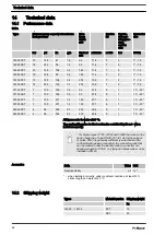
Page 66: ...7 7 5 1 1 1 20 04350 PVT 4 58 352 93 200 29 4 5 1 1 1 20 04350 SST 4 58 352 93 200 29 4 5 1 1 1 20 All figures refer to water at 20 C The suction lift applies to filled suction line and filled liquid end when installed correctly For Sigma types 07120 07220 and 04350 the valves in the dosing head are of type DN 25 G1 1 2 As for these types of pipes DN 20 is generally sufficient see technical data s...

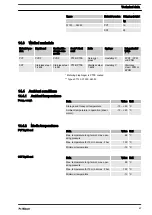
Page 67: ...etering diaphragm is PTFE coated Types 07120 07220 04350 14 4 Ambient conditions 14 4 1 Ambient temperatures Data Value Unit Storage and transport temperature 10 50 C Ambient temperature in operation drive motor 10 40 C 14 4 2 Media temperatures Data Value Unit Max temperature long term at max oper ating pressure 65 C Max temperature for 15 min at max 2 bar 100 C Minimum temperature 10 C Data Valu...

Page 68: ...or electrical data use the motor data sheet 1018455 1018432 1018433 in the appendix Identity code specification power supply U 100 230 V 10 50 60 Hz Electrical data at 100 V Data Value Unit Nominal power 250 W Nominal current 3 2 A Peak current during operation 10 A Switch on peak current for approx 100 ms 12 A Electrical data at 230 V Data Value Unit Nominal power 250 W Nominal current 2 0 A Peak...

Page 69: ... unimportant 5 25 V DC in accordance with Namur or DIN 60947 5 6 potential free design Data Value Unit Nominal voltage 8 VDC Power consumption active surface uncovered 3 mA Power consumption active surface cov ered 1 mA Rated switching distance 1 5 mm Ri 1 kΩ Cable colour Polarity blue brown 14 7 Relay The technical data for the relay are contained in the chapter Installation electrical b Reed swi...

Page 70: ...uired Mobil Mobil Gear 634 VG 460 1004542 1 0 l 0 5 l or comparative gear oil 14 9 Sound pressure level Sound pressure level LpA 70 dB in accordance with EN ISO 20361 2010 10 at maximum stroke length maximum stroke rate maximum back pressure water Sound pressure level Technical data 70 ...

Page 71: ...ring pump Series Sigma Product type S2Ba S2Ca Product type S2Ba S2Ca Serial no refer to nameplate on the device Pertinent EC Machinery Directive 2006 42 EC EC Directives EC Low Voltage Directive 2006 95 EC EC EMC Directive 2004 108 EC Applied harmonised standards EN ISO 12100 1 EN ISO 12100 2 EN 809 in particular EN 60335 1 EN 60335 2 41 EN 60529 EN 61000 3 2 EN 61000 6 2 technical documents have ...

Page 72: ...16 Decontamination declaration Decontamination declaration 72 ...

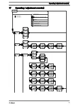
Page 73: ...w Continuous display Stop start pump Change directly changeable variables Lock CODE 1 Lock CODE 2 Prime Start batch only in Batch operating mode Acknowledge errors Check adjustable values P_SI_0040_SW Operating adjustment overview 73 ...

Page 74: ...Set P Set Set Set Calib Set Calib Set Set Set P_SI_0039_SW Operating adjustment overview 74 ...

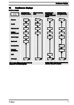
Page 75: ...troke rate Capacity Total number of strokes Total litres metering quantity External display Signal current Remaining strokes Batch size Remaining litres Factor Stroke length B0100 B0101 B0102 B0103 values which can be changed directly using the UP or DOWN arrow keys Identifier Mem only in the event that function extension Memory is activated Continuous displays Continuous displays 75 ...

Page 76: ...ntamination declaration 11 Degree of protection 68 delete 45 48 Deleting the total number of strokes or total litres 48 Diaphragm 16 Diaphragm rupture sensor 13 69 Discharge valve 16 Disposal 65 Dosing head 16 Dosing monitor 47 Drive motor 13 Drive unit 13 15 E Electrical data 68 Emergency 10 Emptying the liquid end 65 Explanation of the safety information 8 External contact 20 32 External frequen...

Page 77: ...ioactive 11 Reduction 44 Reed switch 69 Relief valve 13 25 Repairs 55 Replacing the Diaphragm 57 Replacing the metering diaphragm 57 Reproducibility 66 S Safety chapter 8 Safety requirements 68 Scope of supply 11 SET menu 40 45 Shipping weight 66 Sound pressure level 10 70 Step up 44 Stop 19 20 Storage 11 Storage and transport temperature 67 Stroke length adjustment wheel 13 Suction lift 66 Suctio...

Reviews: