background image

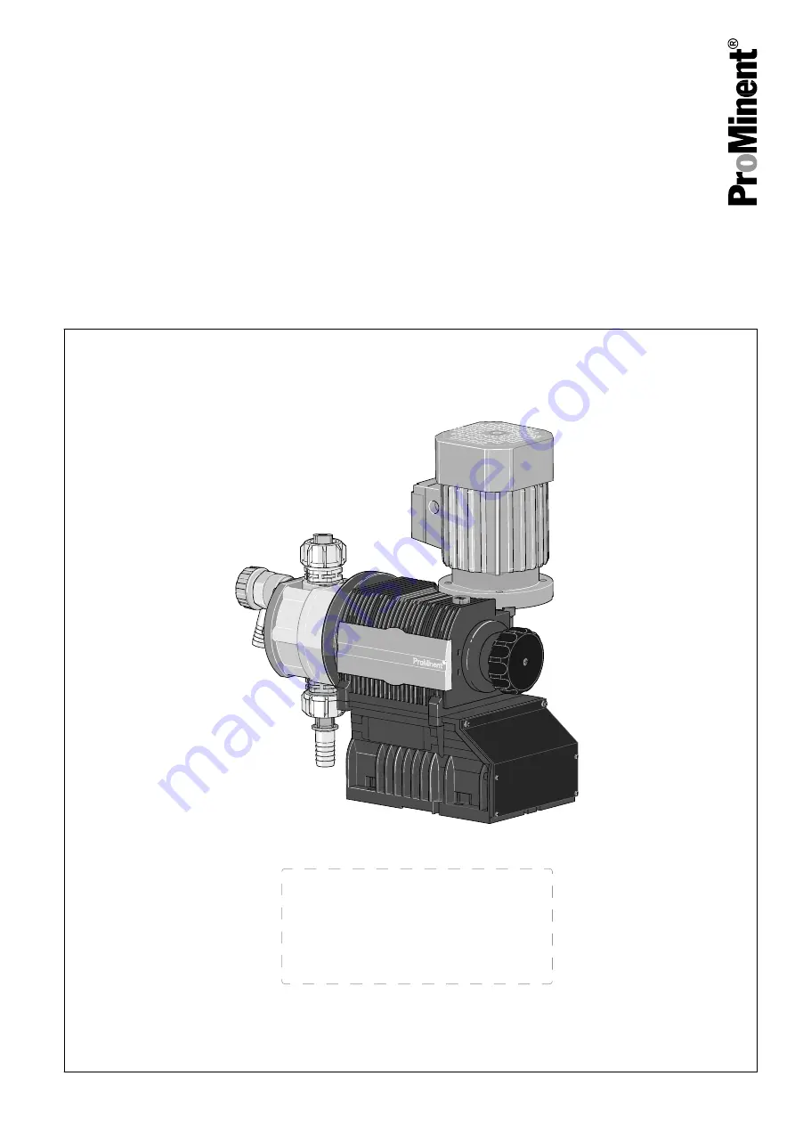
Diaphragm Motor-driven Metering Pump

Sigma/ 1 Basic Type S1Ba

Operating instructions

P_SI_0039

EN

Original Operating Instructions (2006/42/EC)

Part no. 985911

BA SI 075 09/17 EN

Please carefully read these operating instructions before use. · Do not discard.

The operator shall be liable for any damage caused by installation or operating errors.

The latest version of the operating instructions are available on our homepage.

Summary of Contents for Sigma/ 1 Basic S1Ba

Page 1: ...erating Instructions 2006 42 EC Part no 985911 BA SI 075 09 17 EN Please carefully read these operating instructions before use Do not discard The operator shall be liable for any damage caused by ins...

Page 2: ...to the cor rect operation of the unit or is intended to make your work easier Safety notes Safety notes are identified by pictograms see Safety Chapter These operating instructions conform to current...

Page 3: ...59 15 1 Performance data 59 15 2 Viscosity 60 15 3 Shipping weight 61 15 4 Wetted materials 61 15 5 Ambient conditions 61 15 5 1 Ambient temperatures 61 15 5 2 Media temperatures 61 15 5 3 Air humidi...

Page 4: ...23 Declaration of Incorporation for Machinery 87 24 Declaration of Conformity for Machinery ATEX 88 25 Declaration of Incorporation for Machinery 89 26 Index 90 Table of contents 4...

Page 5: ...l no valve springs 5 with relief valve FPM seal with valve springs 6 with relief valve EPDM seal no valve spring 7 with relief valve EPDM seal with valve springs H Hygienic pump head with tri clamp co...

Page 6: ...elay reed relay 3 Stroke sensor Namur for areas at risk from explosion Stroke length adjustment 0 Manual standard 1 With servomotor 230 V 50 60 Hz 2 With servomotor 115 V 50 60 Hz 3 With stroke contro...

Page 7: ...high voltage Warning danger zone n Only use the pump to meter liquid feed chemicals n Only pumps with the identity code option Multi layer safety diaphragm with visual rupture display and Multi layer...

Page 8: ...ation Instructed person Maintenance repair Technical personnel Service Decommissioning disposal Technical personnel Service Troubleshooting Qualified person electrical techni cian instructed person se...

Page 9: ...zardous substances Possible consequence Fatal or very serious injuries Please ensure when handling hazardous substances that you have read the latest safety data sheets provided by the manufacture of...

Page 10: ...sure that the pump is accessible at all times Adhere to the maintenance intervals In the event of an electrical accident disconnect the mains cable from the mains or press the emergency cut off switch...

Page 11: ...pressure water 2 1 Safety information for ATEX designs This chapter lists all safety information for ATEX designs Safety informa tion is listed again at the relevant points in these operating instruc...

Page 12: ...ea in which he is employed and be familiar with the relevant standards and regulations The skilled technician with an additional explosion protection qualification can work on equipment and systems in...

Page 13: ...ive when operating equipment in areas at risk of explo sion Only clean plastic parts carefully with a damp cloth to avoid electrostatic charges and sparks WARNING Motor may overheat If the necessary c...

Page 14: ...ive media are being metered they will escape as soon as all layers of the diaphragm have eroded through Wire the electrical diaphragm rupture indicator to stop the pump in the event of a diaphragm rup...

Page 15: ...the leakage point immediately and eliminate the cause Check the correct operation of the relief valve down stream of the pump In premises at risk from explo sion the relief valve should prevent the ge...

Page 16: ...e NJ1 5 8GM N Measure the surface temperature at maximum load Additional information refer to the operating instructions for the gear Check the pump installation for n Leaks n Abnormal noises or squea...

Page 17: ...always fitted and legible Do not allow other labels to be stuck over this label electrostatic charging hazard see instructions Potential Warning Fig 2 The operator must be able to n with ATEX motors p...

Page 18: ...erating instructions The Declarations of Conformity can be found at the end of the operating instructions If there is an X at the end of the ATEX specification of a unit in a Decla ration of Conformit...

Page 19: ...rial damage The device can be damaged by incorrect or improper storage or transportation The unit should only be stored or transported in a well packaged state preferably in its original pack aging Th...

Page 20: ...pment and control elements S1Ba 1 Drive motor 2 Drive unit 3 Stroke length adjustment knob 4 Liquid end with relief valve 5 Diaphragm rupture sensor 1 2 P_SI_0088_SW Fig 4 Sigma control elements 1 Rel...

Page 21: ...oke length n 100 2 rotations n 50 1 rotation n 1 1 scale mark on stroke adjustment dial PG11 PG9 1 2 3 A B P_SI_0036 Fig 6 Front cover for version with pacing relay A Pacing relay cable B Supply volta...

Page 22: ...One cycle is thus completed 4 2 1 5 3 13 Fig 7 Cross section through the liquid end 1 Suction valve 2 Diaphragm 3 Discharge valve 4 Dosing head 5 Backplate 13 Safety diaphragm 5 3 Integral relief valv...

Page 23: ...in the event of a diaphragm rup ture the lowered red cylinder 6 springs forward beneath the transparent cover 7 so that it then becomes clearly visible see Fig 9 With the electrical diaphragm rupture...

Page 24: ...ight see Fig 10 3 Secure set screws and threaded connections to prevent them from loosening WARNING EX is relevant in areas at risk from explosion 4 As you have converted an incomplete machine into a...

Page 25: ...y overheat In an area at risk from explosion it could trigger an explosion Maintain sufficient clearance between the air intake opening and the walls The distance should be greater than 1 4 of the dia...

Page 26: ...discharge valve is upright Capacity too low Vibrations can disturb the liquid end valves Secure the metering pump so that no vibrations can occur Take the dimensions m for the fastening holes from the...

Page 27: ...media but fundamentally only those designed with an ATEX diaphragm rupture sensor and a discharge side flow control which both stop the pump as soon as a diaphragm rupture or no flow is detected Durin...

Page 28: ...m permissible operating pres sure of the system CAUTION Uncontrolled flow of feed chemical Feed chemical can press through a stopped metering pump if there is back pressure Use an injection valve or a...

Page 29: ...and then only against impermissible positive pressure that is caused by the metering pump itself It cannot protect the system against positive pressure Protect the motor and gear of the system agains...

Page 30: ...k into the storage tank When operating the integral relief valve close to the opening pressure a minimal overflow into the overflow line can occur CAUTION Danger resulting from unnoticed diaphragm rup...

Page 31: ...azardous feed chemicals Hazardous feed chem ical can leak out when using conventional bleeding pro cedures with metering pumps Install a bleed line with a return into the storage tank Shorten the retu...

Page 32: ...for the individual electrical components WARNING Danger of fire with flammable feed chemicals The ATEX diaphragm rupture sensor and a dis charge side flow control must both stop the pump as soon as a...

Page 33: ...fre quency converter Only open the drain screw 3 minutes after the mains voltage has been switched off WARNING Never change the Motor voltage and Cycle frequency parameters with motor designs with int...

Page 34: ...ppropriate motor protection devices e g motor protection switch with thermal overcurrent trip to protect the motor from overloading Fuses do not provide motor protection CAUTION Operation of the syste...

Page 35: ...s special motors special motor flanges external fan temperature monitoring For further information on the motor with identity code specification S refer to our website www prominent com Motor data she...

Page 36: ...le can be connected as required b Namur sensor inherently safe Make sure that the monitoring feed equipment installed by the customer is capable of evaluating the current variations of the Namur senso...

Page 37: ...relay becomes too high it can be destroyed by heating Fit a circuit breaker Pacing relay terminal output data Data Value Unit Maximum voltage 24 VDC Maximum current 100 mA Closing duration approx 100...

Page 38: ...necessary potential equalisation lines Electrically connect an additional potential equalisation cable from the potential equalisation cables from this system cleanly and permanently to an electrical...

Page 39: ...er of elec tric shock The danger of electric shock remains for 3 minutes after the mains voltage has been switched off on conducting parts of the motor with an integrated frequency converter and on th...

Page 40: ...material damage Observe the details in the chapter Technical data pressure viscosity resistance etc Check that the installation complies with the regulations CAUTION Danger resulting from unnoticed d...

Page 41: ...t cannot protect the system against positive pressure Protect the motor and gear of the system against positive pressure using other mechanisms Protect the system against illegal positive pressure usi...

Page 42: ...1 scale mark on stroke adjustment dial Check whether the earthing lines in the pump s electrical units are cor rectly connected and connected to a clean earth wire see earthing dia grams in the appen...

Page 43: ...injury and material damage may occur During use all units protective equipment additional devices must be fitted operational and tightly closed WARNING Sparking caused by dry running If the bearings i...

Page 44: ...be at a different electrical potential such as pipes or tools Only with stroke control motor Wait 3 minutes after switching off before opening the housing Replace wear parts such as bearings when ther...

Page 45: ...arning of hazardous feed chemical Should a dangerous feed chemical be used it may escape from the hydraulic components when working on the pump material failure or incorrect handling of the pump Take...

Page 46: ...seated n Check whether the diaphragm rupture sensor stops the pump or generates an alarm after it has been triggered n Check that the flow is correct Allow the pump to prime briefly Observe the maximu...

Page 47: ...ing of the diaphragm is rec ommended Data Value Unit Tightening torques for dosing head screws 4 5 5 0 Nm WARNING Warning of eye injuries When opening the relief valve a spring under high ten sion can...

Page 48: ...ning of feed chemical spraying around Feed chemical can spray out of the hydraulic compo nents if they are manipulated or opened due to pressure in the liquid end and adjacent parts of the system Disc...

Page 49: ...cal personnel CAUTION Warning of personal injury and material damage Feed chemical may escape from the liquid end for example if ball valves not repaired correctly Only use new components which fit yo...

Page 50: ...he stop at 0 stroke length The drive axle is now difficult to turn 3 Switch off the pump 4 Unscrew the hydraulic connectors on the discharge and suction side 5 Unscrew the diaphragm rupture sensor fro...

Page 51: ...N Warning of escaping feed chemical The liquid end may leak should it not be possible to check the tightening torque of the screws Check the tightening torque of the screws after 24 hours of operation...

Page 52: ...s the red cylinder into the diaphragm rupture sensor again and repeat the test 5 If it does not trigger both times replace the membrane rupture sensor 6 After a successful test screw the transparent c...

Page 53: ...section through the liquid end 1 Suction valve 2 Diaphragm 3 Discharge valve 4 Dosing head 5 Backplate 13 Safety diaphragm Data Value Unit Tightening torques for dosing head screws 4 5 5 0 Nm Tighten...

Page 54: ...be ignited by oxygen The pump may not work if there is a mixture of feed chemical with oxygen in the liquid end A specialist may need to take appropriate actions using inert gas WARNING Danger of an...

Page 55: ...cing any work on hydraulic parts Fault description Cause Remedy Personnel Pump does not prime in spite of full stroke motion and bleeding The valves are dirty or worn Repair the valves see chapter ent...

Page 56: ...plosion under no circumstances must the second diaphragm also rupture If the pump diaphragm rupture sensor triggers stop the pump immediately and only operate once a new multi layer safety diaphragm h...

Page 57: ...l residues There is normally chemical residue in the liquid end and on the housing after operation This chemical residue could be hazardous to people It is mandatory that the safety information in the...

Page 58: ...storage and transport Take into account the information in the Storage Transport and Unpacking chapter if the system is decommissioned for a temporary period 1 Disconnect the pump from the mains power...

Page 59: ...12 35 4 0 143 7 1 3 4 10 10050 PVT 10 50 4 0 205 7 1 3 4 10 10050 SST 10 50 4 0 205 7 1 3 4 10 10022 PVT 10 22 5 0 73 6 1 3 4 10 10022 SST 10 22 5 0 73 6 1 3 4 10 10044 PVT 10 44 5 1 143 6 1 3 4 10 1...

Page 60: ...5 SST 7 102 78 20 6 246 6 1 3 4 10 07042 PVT 7 102 50 13 2 88 3 1 1 15 07042 SST 7 102 50 13 2 88 3 1 1 15 04084 PVT 4 58 100 26 6 172 3 1 1 15 04084 SST 4 58 100 26 6 172 3 1 1 15 04120 PVT 4 58 144...

Page 61: ...inless steel FPM or EPDM TTT PTFE 25 carbon PVDF PTFE PTFE Ceramic Hastelloy C4 PVDF FPM or EPDM Diaphragm is PTFE coated 15 5 Ambient conditions 15 5 1 Ambient temperatures Data Value Unit Storage an...

Page 62: ...ecialist for ATEX motors at higher installation heights 15 7 Motor data Identity code specification Phases protec tion Rated voltage Mains frequency Rated output Remarks S 3 phase IP 55 220 240 V 380...

Page 63: ...code specification S refer to our website www prominent com Motor data sheets can be requested for all other motors With motors other than those with identity code specifications S M or N Pay special...

Page 64: ...947 5 6 potential free design Data Value Unit Nominal voltage 8 VDC Power consumption active surface uncovered 3 mA Power consumption active surface cov ered 1 mA Rated switching distance 1 5 mm Ri 1...

Page 65: ...um stroke rate maximum back pressure water 15 14 Supplementary information for modified versions With identity code specification Version M modified Technical data of pumps in the modified version can...

Page 66: ...With a modified version it is absolutely necessary to specify the details of the serial number requesting and ordering the spare and replacement parts Spare parts Technical data 66...

Page 67: ...B 0 10 20 30 40 50 60 70 80 90 100 0 0 10 0 20 0 30 0 40 0 50 0 60 0 70 0 07065 10044 10022 0 0 10 0 20 0 30 0 40 0 50 0 60 0 70 0 80 0 0 0 1 0 2 0 3 0 4 0 5 0 6 0 7 0 8 0 9 0 10 11 0 07065 10044 1002...

Page 68: ...0 40 0 60 0 80 0 100 0 120 0 140 0 160 0 0 0 1 0 2 0 3 0 4 0 5 0 6 0 7 0 04120 04084 07042 0 0 160 0 04120 04084 07042 12 0 p bar S C l h C l h A B 0 10 20 30 40 50 60 70 80 90 100 0 0 10 0 20 0 30 0...

Page 69: ...F G I K Sigma 12017 12035 10050 PVT DN10 233 147 G 3 4 A 91 277 96 Sigma 12017 12035 10050 PVT relief valve A sv a DN10 233 147 G 3 4 A 91 280 84 96 131 61 Sigma 12017 12035 10050 SST DN10 231 142 G...

Page 70: ...07042 04085 04120 PVT relief valve A sv a DN15 242 165 G 1 A 96 296 74 122 138 63 Sigma 07042 04085 04120 SST DN15 242 165 G 1 A 95 285 122 Sigma 07042 04085 04120 SST relief valve A sv a DN15 242 165...

Page 71: ...1 267 105 Sigma 12017 12035 10050 SST relief valve A sv a DN10 231 142 G 3 4 A 61 267 88 105 100 45 Sigma 10022 10044 07065 PVT DN10 233 147 G 3 4 A 62 269 96 Sigma 10022 10044 07065 PVT relief valve...

Page 72: ...or Motor with fre quency converter 1 phase motor L 379 416 420 519 399 P_SI_0034_2 61_01 101_00_55 73 Fig 29 Dimensional drawing of Sigma 1 S1Ba motor flange actuator Drawing is not strictly binding T...

Page 73: ...142 G 3 4 A 70 267 105 Sigma 12017 12035 10050 SST relief valve A sv a DN10 237 142 G 3 4 A 70 267 88 105 106 45 Sigma 10022 10044 07065 PVT DN10 239 147 G 3 4 A 70 269 96 Sigma 10022 10044 07065 PVT...

Page 74: ...04084 04120 PVT relief valve A sv a DN15 248 165 G 1 A 75 288 74 122 144 63 Sigma 07042 04084 04120 SST DN15 249 165 G 1 A 74 277 122 Sigma 07042 04084 04120 SST relief valve A sv a DN15 249 165 G 1 A...

Page 75: ...Potential equalisation drawing for Sigma S1Ba 1 Potential equalisation of motor 2 Potential equalisation of motor flange 3 Potential equalisation of liquid end Positions 1 2 and 3 must be connected to...

Page 76: ...Bauform B5 Bemessungsdrehzahl 1350 1620 U min mounting rated speed rpm Bemessungsleistung 0 09 kW W rmeklasse F rated output temperature class Bemessungsspannung Anzugsstrom 2 6 fach rated voltage 50...

Page 77: ...10022 1 Spring 2 Ball 3 Ball seat 4 Diaphragm rupture sensor visual 1033323 1033323 5 Valve 1002267 1002267 6 Multi layer diaphragm 1030114 1030115 The items listed are included in the spare parts ki...

Page 78: ...ng 2 Ball 3 Ball seat 4 Diaphragm rupture sensor visual 1033323 5 Valve 792517 6 Multi layer diaphragm 1035828 The items listed are included in the spare parts kit Special accessories not included in...

Page 79: ...ve complete 12 bar PVA 1018572 10 Relief valve complete 10 bar PVA 1018947 10 Relief valve complete 7 bar PVA 740811 10 Relief valve complete 4 bar PVA 740812 The items listed are included in the spar...

Page 80: ...ing 2 Ball 3 Ball seat 4 Diaphragm rupture sensor visual 1033323 1033323 5 Valve 809459 809459 6 Multi layer diaphragm 1030114 1030115 The items listed are included in the spare parts kit Special acce...

Page 81: ...ing 2 Ball 3 Ball seat 4 Diaphragm rupture sensor visual 1033323 5 Valve 809404 6 Multi layer diaphragm 1035828 The items listed are included in the spare parts kit Special accessories not included in...

Page 82: ...625 10 Relief valve complete 10 bar SSA 1018573 10 Relief valve complete 7 bar SSA 740815 10 Relief valve complete 4 bar SSA 740814 The items listed are included in the spare parts kit Springs made fr...

Page 83: ...nner part TCVC with seal 1038124 122 A C 2 000 Hyg valve interior without seal TCVC 1038922 123 A B 1 000 Hyg valve top part TCVC DN10 1035919 123 C 1 000 Hyg valve top part TCVC DN15 1035933 124 A B...

Page 84: ...0 FM 50 DN10 1035966 FM 50 DN10 with 2 complete valves 1035965 FM 65 DN10 1035969 FM 65 DN10 with 2 complete valves 1035968 FM 120 DN15 1035963 FM 120 DN15 with 2 complete valves 1035962 Scope of deli...

Page 85: ...Tab 13 Spare parts kits SST liquid ends Liquid end Types 12017 12035 10050 Types 10022 10044 07065 Types 07042 04084 04120 FM 50 DN 10 1046468 FM 50 DN 10 with 2 com plete valves 1046467 FM 65 DN 10 1...

Page 86: ...Extract from the Declaration of Conformity Designation of the product Metering pump Sigma product range Product type S1Ba _ _ _ _ _ _ _ _ _ _ _ _ _ _ 0 _ _ with characteristics M or N or R or S or T o...

Page 87: ...o the product not approved by us will invalidate this dec laration Tab 15 Extract from the Declaration of Conformity Designation of the product Metering pump without motor product range Sigma Product...

Page 88: ...he device Relevant directives ATEX Directive 2014 34 EC Machinery Directive 2006 42 EC Compliance with the protection targets of the Low Voltage Directive 2014 35 EU according to Appendix I No 1 5 1 o...

Page 89: ...explosion in accordance with the ATEX Direc tive 2014 34 EC Product type S1Ba _ _ _ _ _ _ _ _ _ _ _ _ _ _ A _ _ with characteristics 2 or 3 or G Serial number see nameplate on the device Relevant dir...

Page 90: ...xternal fan 34 62 F Form 65 G Guard plate 62 I Identification of safety notes 7 Identity code 5 Information in the event of an emergency 10 Installation 27 Installation height 62 Installation electric...

Page 91: ...perature 61 Stroke actuator 63 Stroke control drive 63 Stroke length 42 Stroke length adjustment control 65 Stroke length adjustment knob 20 Stroke sensor 36 64 Suction lift 59 60 Suction valve 22 Sym...

Page 92: ...Heidelberg 4 en_GB 2011 ProMinent GmbH Im Schuhmachergewann 5 11 69123 Heidelberg Germany Telephone 49 6221 842 0 Fax 49 6221 842 419 Email info prominent com Internet www prominent com...

Reviews: