2.3 Installation, hydraulic
Maximum particle size of the feed chemical: 0.3 mm
Connection to the pipework system: It is the responsibility of the customer
to provide the corresponding parts in compliance with DIN 11864.
The correct 2 O-rings in compliance with DIN 11864 R are supplied sepa‐
rately.
Take into account the resistance of the wetted materials and the ProMi‐
nent Resistance List when selecting the feed chemical - see the ProMinent
Product Catalogue or visit our website.
The construction of the discharge and suction valve of the pump tapers
the overall cross-section. Therefore, if necessary, install a correctly fitting
bypass with shut-off valves around the liquid end to flush your system.
Provide the corresponding connectors and valves upstream and down‐
stream of the liquid end if the liquid end needs to be regularly purged (it
contains check valves). Pay attention to the quality of the compressed air ‐
to match your process!
2.4 Start up
Use a suitable medium to rinse the pump.
2.5 Maintenance
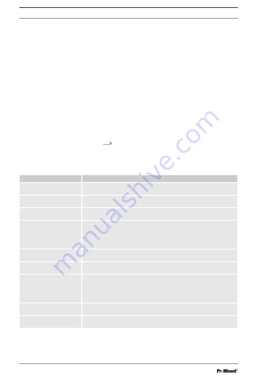
Tab. 6: Maintenance intervals
Maintenance interval
Maintenance work
Regularly *
Flush the interior of the liquid end - see
Chapter 3 ‘Notes on cleaning metering
pumps with hygienic pump head’ on page 20
Regularly *
Switch off the mains voltage and flush the pump with a surge of water from a hose
at atmospheric pressure.
Regularly *
Check the surfaces and seals for scratches and deposits - refer to
.
Regularly *
Check the seals of the hygiene valve and replace them if in doubt - refer to the
appropriate chapter “Spare parts lists” and
Chapter 3.3 ‘Cleaning, manual’
.
The O-rings can age faster than usual when exposed to high thermal loading - in
extreme cases, particles can enter the feed chemical.
If damaged or worn
Immediately replace the relevant parts of the hygiene valve - refer to the appropriate
chapter “Spare parts lists” and
Chapter 3.3 ‘Cleaning, manual’ on page 23
If the pump is leaking at a valve
Immediately replace the relevant parts of the hygiene valve - refer to the appropriate
chapter “Spare parts lists” and
Chapter 3.3 ‘Cleaning, manual’ on page 23
Annually *
Replace the O-rings, the valve balls and the multi-layer diaphragm - refer to the
appropriate chapter “Spare parts lists” and
Chapter 3.3 ‘Cleaning, manual’
.
Turn the valve seats over if the worn side can be mechanically machined so that it is
still suitable for hygienic operation. Otherwise replace.
Every 2 years *
Replace the valve seats - refer to the relevant chapter “Spare parts lists” and
Chapter 3.3 ‘Cleaning, manual’ on page 23
.
At the latest after 8,000 oper‐
ating hours
Replace all worn parts - refer to the relevant chapter “Spare parts lists” and
Chapter 3.3 ‘Cleaning, manual’ on page 23
.
* adapted to your process conditions and process requirements
General information
18

