background image


To modify the threshold values: 


 Press 

SEL 

 to move along the parameters. 


  To change a parameter, it must be shaded. Once it is shaded it can be 

modified by using the arrows. 


  Once changes are made, press again SEL 

 to get out from editing the 

parameter. 


  To get out from the configuration mode and back to the main menu press 

CONFIG 


3.2.5    LOGGER Function 


LOGGER function takes data and save them on the memory, so they can be 
viewed or downloaded on a computer. 


Each funtion has its own logger memory up to 99 loggers par function. 


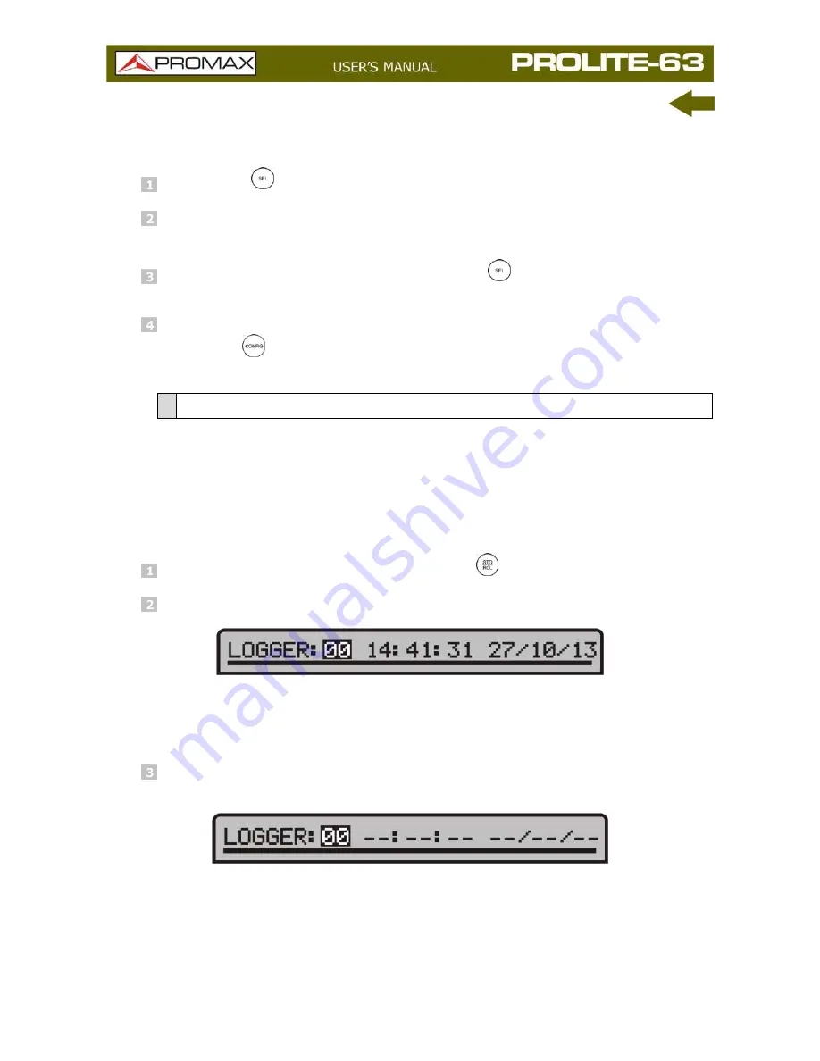
To access the LOGGER Function


  From the function you are press STO/RCL 

. 


  Upper line on the screen changes (see figure below). 


Figure 7. Logger. 


In this line is shown the last logger accessed and date and hour when was 
taken. 


  If the upper line does not show date and hour means that the register is 

empty (see figure below). 


Figure 8. Empty Register. 


12 

January 2014 

Summary of Contents for PROLITE-63

Page 1: ...PROLITE 63 FTTH OPTICAL POWER METER 0 MI2003...

Page 2: ......

Page 3: ...quipment means SEE USER S MANUAL In this manual may also appear as a Caution or Warning symbol WARNING AND CAUTION statements may appear in this manual to avoid injury hazard or damage to this product...

Page 4: ......

Page 5: ...gree 1 environments It is for INDOOR USE When using some of the following accessories use only the specified ones to ensure safety Power adapter Car cigarette lighter adapter Mains cord Observe all sp...

Page 6: ...y Descriptive Examples of Over Voltage Categories Cat I Low voltage installations isolated from the mains Cat II Portable domestic installations Cat III Fixed domestic installations Cat IV Industrial...

Page 7: ...11 3 2 5 LOGGER Function 12 3 3 Connecting to a computer 14 4 CONTROL SOFTWARE PROLITE 63 15 4 1 Description 15 4 2 Hardware and software Requirements 15 4 3 Installation 16 4 3 1 Software Installati...

Page 8: ...January 2014...

Page 9: ...to identify optic fibre measure simultaneously optical attenuation for GPON networks 1310 nm 1490 nm and 1550 nm verify continuity and evaluate fibre link transmission quality It also has a logger fun...

Page 10: ...nt starts working CAUTION Before using the mains adapter make sure that it is the appropriate one for your mains voltage 2 1 2 Operation Using the Battery Press the key ON OFF 1 to start the instrumen...

Page 11: ...a long period of inactivity for your instrument it is advisable to store it with the battery fully charged and at temperatures below 25 C It is also advisable in these cases to carry out a cycle of c...

Page 12: ...ain Menu Screen It moves the cursor over the functions Function Screen It shows the available values in the selected field Attenuation Test OPM Screen It captures a value to use as a reference by pres...

Page 13: ...lue to measure from it OPTICAL LOSS TEST SET It measures the attenuation for GPON networks by identificating modulation of 270 Hz for 1310 nm 1 kHz for 1490 nm and 2 kHz for 1550 nm THRESHOLD CONFIGUR...

Page 14: ...to configurate the system Fig 3 Figure 3 SETUP Screen To edit the status or change a parameter value Press or to move along the menu Place the arrow pointing at the parameter to modify and press SEL T...

Page 15: ...LCD CONSTRAST This parameter allows you to change the screen contrast AUTO POWER OFF This parameter lets you define a time for the instrument automatic shutdown After this time without pressing any k...

Page 16: ...ency Graphical representation of the power Selected threshold group of values Threshold values are grouped and saved on the memory of the instrument then later they can be selected in order to the qua...

Page 17: ...t it and press or To capture a new reference value select the current reference value and press both keys and simultenously To make or consult a logger refer to the section LOGGER Function 3 2 3 OPTIC...

Page 18: ...0 nm corresponds to the UPSTREAM and the other two 1490 y 1550 nm to the DOWNSTREAM Signal status with respect to threshold values Three status are possible PASS HIGH LOW Power graphical representatio...

Page 19: ...it and press or To capture a new reference value select the current reference value and press both keys and simultenously To make or consult a logger refer to the section LOGGER Function 3 2 4 THRESHO...

Page 20: ...Function LOGGER function takes data and save them on the memory so they can be viewed or downloaded on a computer Each funtion has its own logger memory up to 99 loggers par function To access the LOG...

Page 21: ...nt date and hour To consult a logger press SEL From this screen you can move between registers by pressing or If you move to an empty logger it appears the message No data To return to the function sc...

Page 22: ...mputer This instrument allows you to be connected to a personal computer via USB in order to download registers and to update firmware For more information see next chapter about PROLITE 63 control so...

Page 23: ...and configure some other parameters It also allows upgrading the instrument 4 2 Hardware and software Requirements In order to use the program your computer system need to meet the next requerements H...

Page 24: ...he section Operation Instructions is explained in detail the program operation 4 4 LEGAL CONDITIONS Read the contract carefully in its entirety before you install the program Installing the program me...

Page 25: ...rmation it contains and generates Nor can PROMAX ELECTRONICA S L be held liable for the suitability or accuracy of the data obtained for particular purposes or functions since the only obligation of t...

Page 26: ...message Synchronizing USB with PC Figure 12 Figure 12 If the instrument detects the control program is not running will give the message PC software is not detected Figure 13 The program must be star...

Page 27: ...3 is ON Check connection between PROLITE 63 and computer Run the program by double clicking on the icon PROLITE 63 which is located on the desktop The main window appears see figure below Figure 14 PR...

Page 28: ...to perform various operations with loggers 5 When the instrument PROLITE 63 is identified at the USB port it shows on screen some data about it such serial number and model LEGAL NOTICE In any case PR...

Page 29: ...cted language Active function selection tab There are four tabs corresponding to each one of the two functions that are available at the program They are Optical Power Meter and Optical Loss Test Set...

Page 30: ...ctive function Save Loggers to PC It saves the selected loggers in a file A navigation window pops up where you can select the folder where you want to save the file The file has an extension associat...

Page 31: ...ailable options in the instrument Editors It contains the option to edit upper and lower threshold values of each group Language It contains the options to select the language in use at the program Up...

Page 32: ...such as import data view loggers make reports etc This option is equal to click on the tab corresponding to the option you want to activate 5 3 3 Editors It contains the option Threshold Through this...

Page 33: ...ons The Firmware option allows you to update the firmware of the instrument PROLITE 63 through upgrading files that can be obtained from the PROMAX webpage Clicking on this option you open a navegatio...

Page 34: ...i mode ALIMENTATION Battery 7 4 V Li Ion Battery Low Battery Indicator Graphic indicator on screen Operating time Approx 25 h Battery Charging By fast internal charger External Voltage 12 V DC Consump...

Page 35: ...le car 1x DC 272 Protective cover 1x CA 05 Mains cord CEE 7 1x CC 41 Data Transfer Cable USB to PC Wrist Strap CD ROM PROLITE 63 Adaptor s Kit SC FC and ST 1x DG0136 Guide Reference rapide OPTIONAL AC...

Page 36: ...over and changing the battery All other operations must be carried out by authorised agents or by qualified personnel 7 2 1 Cleaning the cover CAUTION Do not use scented hydrocarbons or chlorized solv...

Page 37: ...January 2014 29 7 2 2 Not replaceable fuses by user F001 FUS 2 5 A T 125 V F002 FUS 7 A T 125 V...

Page 38: ...le or optical device corresponds to the difference between the input coupled power and the output obtained power Measuring the reference power Before initiating the network attenuation measurement pro...

Page 39: ...on measurement in the optical communications network Next the procedure to take the measurement is described see figure Figure A2 Attenuation measurement in the optical communications network Connect...

Page 40: ...Francesc Moragas 71 75 08907 L HOSPITALET DE LLOBREGAT Barcelona SPAIN Tel 93 184 77 00 Tel Intl 34 93 184 77 02 Fax 93 338 11 26 Fax Intl 34 93 338 11 26 http www promaxelectronics com e mail promax...

Reviews: