17
11.0
User-Maintenance
WARNING:
Before any intervention on the machine, disconnect it from
electrical supply, pull the mains plug. Failure to comply may
cause serious injury.
An important security factor is the cleaning of the machine, of
bed, carriage and slides, of the floor and the surrounding
places.
Loose objects could come into contact with the moving chuck
or workpiece, creating hazards.
Empty the chip tray regularly.
Replace the coolant regularly, follow manufacturer’s advice.
Check that bolts are tight and electrical cords are in good
condition. If an electrical cord is worn, cut, or damaged in any
way, have it replaced immediately.
11.1
Lubrication
Spindle bearings are pre-lubricated and sealed, and require no
further lubrication.
A) Weekly apply oil:
DIN 51502 CG ISO VG 68
(e.g. BP Maccurat 68, Castrol Magna BD 68, Mobil Vectra 2)
1…oil balls on change gear hubs
2…oil bed ways lightly
3…oil tailstock quill over entire length
4…oil lead screw on entire length
5…oil ball on lead screw bracket
6…oil balls on top slide
7…oil balls on tailstock
8...oil balls on carriage
9...oil balls on apron
B) Monthly apply grease:
DIN 51807-1 non slinging grease
(e.g. BP L2, Mobilgrease Special).
10…grease teeth of change gears
11…grease rack over entire length
Gear box oil:
DIN 51517-2 CL ISO VG 68
(e.g. BP Energol HLP 68, Mobil DTE Oil Heavy Medium)
Oil must be up to indicator mark in oil sight glass (L, Fig 11-1).
In case of need, fill oil by removing plug (M).
Figure 11-1: Gearbox oil fill-up
Change the oil in the gearbox every 1000 operating hours.
Drain oil by removing drain plug (K).
11.2
Readjustments
A) Bearing adjustment:
The main spindle taper roller bearings are adjusted at the
factory.
If end play becomes evident after considerable use the
bearings may be adjusted.
Loosen two hex socket cap screws (A, Fig 11-2). Tighten nut (B)
until end play is taken up.
Figure 11-2: Bearing adjustment
Tighten nut carefully, the spindle should still revolve freely.
Excessive preloading will damage the bearings.
Tighten the screws.
Summary of Contents for PBD-2870
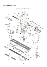
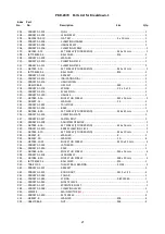
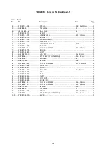
Page 20: ...20 15 0 Replacement Parts PBD 2870 Assembly Breakdown 1 ...
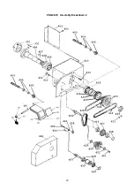
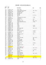
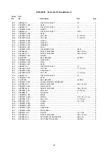
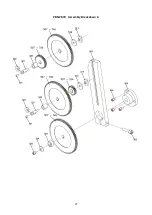
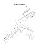
Page 23: ...23 PBD 2870 Assembly Breakdown 2 ...
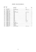
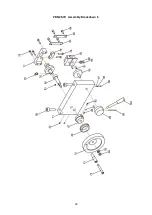
Page 25: ...25 PBD 2870 Assembly Breakdown 3 ...
Page 27: ...27 PBD 2870 Assembly Breakdown 4 ...
Page 29: ...29 PBD 2870 Assembly Breakdown 5 ...
Page 31: ...31 PBD 2870 Assembly Breakdown 6 ...
Page 33: ...33 PBD 2870 Assembly Breakdown 7 ...
Page 39: ...39 16 0 Wiring Diagrams PBD 2870 1 230V PE 50Hz ...
Page 58: ...58 15 0 Ersatzteile PBD 2870 Explosionszeichnung 1 ...
Page 60: ...60 PBD 2870 Explosionszeichnung 2 ...
Page 62: ...62 PBD 2870 Explosionszeichnung 3 ...
Page 64: ...64 PBD 2870 Explosionszeichnung 4 ...
Page 66: ...66 PBD 2870 Explosionszeichnung 5 ...
Page 68: ...68 PBD 2870 Explosionszeichnung 6 ...
Page 70: ...70 PBD 2870 Explosionszeichnung 7 ...
Page 72: ...72 16 0 Schaltplan PBD 2870 1 230 V PE 50 Hz ...
Page 91: ...91 15 0 Pièces de rechange PBD 2870 Vue explosée 1 ...
Page 93: ...93 PBD 2870 Vue explosée 2 ...
Page 95: ...95 PBD 2870 Vue explosée 3 ...
Page 97: ...97 PBD 2870 Vue explosée 4 ...
Page 99: ...99 PBD 2870 Vue explosée 5 ...
Page 101: ...101 PBD 2870 Vue explosée 6 ...
Page 103: ...103 PBD 2870 Vue explosée 7 ...
Page 105: ...105 16 0 Schémas de câblage PBD 2870 1 230V PE 50Hz ...


