Promac 941VA Operating Instructions Manual Download Page 10


S

ECTION 2: POWER SUPP LY 


Availability 

Before installing the machine, consider the 
availability and proximity of the required 
power supply circuit. If an existing circuit 
does not meet the requirements for this 
machine, a new circuit must be installed. 
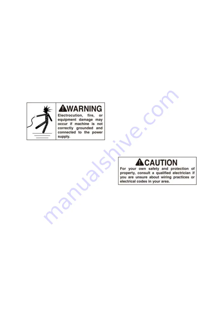
To minimize the risk of electrocution, 
fire, or equipment damage, installation 
work and electrical wiring must be done by 
a qualified electrician in accordance with 
all applicable codes


and standards.  


Full-Load Current Rating 

The full-load current rating is the amperage 
a machine draws at 100% of the rated 
output power. On machines with multiple 
motors, this is the amperage drawn by the 
largest motor or sum of all motors and 
electrical devices that might operate at one 
time during normal operations. 
 

Full-Load Current Rating at 230V.... 6 
Amps 


The full-load current is not the


maximum 

amount of amps that the machine will draw. 
If the machine is overloaded, it will draw 
additional amps beyond the full-load rating. 
 
If the machine is overloaded for a sufficient 
length of time, damage, overheating, or fire 
may result— especially if connected to an 
undersized circuit. To reduce the risk of 
these hazards, avoid overloading the 
machine during operation and make 
sure it is connected to a power supply 
circuit that meets the requirements in the  
following section. 

Circuit Requirements


This machine is prewired to operate on a 
110V power supply circuit that has a 
verified ground and meets the following 
requirements: 


Voltage..........................................220V/240V 
Frequency..............................................50 Hz 
Phase...........................................Single-Phase 
Power Supply Circuit......................10 Amps


A power supply circuit includes all 
electrical equipment between the breaker 
box or fuse panel in the building and the 
machine. The power supply circuit used for 
this machine must be sized to safely handle 
the full-load current drawn from the 
machine for an extended period of time. (If 
this machine is connected to a circuit 
protected by fuses, use a time delay fuse 
marked D.) 


Note: 

The circuit requirements listed in this 

manual apply to a dedicated circuit—where 
only one machine will be running at a time. 
If this machine will be connected to a 
shared circuit where multiple machines will 
be running at the same time, consult a 
qualified electrician to ensure that the 
circuit is properly sized for safe operation. 


8

Summary of Contents for 941VA

Page 1: ...structions M BD 941VA M Schweiz Suisse JPW TOOL AG T mperlistrasse 5 CH 8117 F llanden Switzerland www promac ch France TOOL France PROMAC 57 rue du Bois Chaland Z I du Bois Chaland case postale 2935...

Page 2: ...irective Maschinenrichtlinie Directive Machines 2014 30 EU electromagnetic compatibility elektromagnetische Vertr glichkeit compatibilit lectromagn tique designed in consideration of the standards und...

Page 3: ...1...

Page 4: ...stall belt and Chang speeds 13 Test Run Lathe 14 SECTION 4 OPERATE 15 General 15 Controls 15 Removing Installing Chuck or Faceplate 16 Dead Centers 17 Tailstock Positioning 18 Changing Tool Posts 18 C...

Page 5: ...terminology used in this manual 1 Speed of Spindle rpm 2 Emergency Stop Switch 3 Stop Button 4 Speed Control Knob 5 Emergency Stop Switch 6 Start Button 7 Carriage Handwheel 8 Cross Slide Handwheel 9...

Page 6: ...power 1000W Amps 6 amp 230v Speed 3600 RPM Speeds 1 Power Transfer Belt Drive to Gear Bearings Shielded and Permanently Lubricated Main Specifications Operation Info Swing Over Bed 250 mm Distance Bet...

Page 7: ...ds 6 Range of Inch Threads 10 44 TPI Number of Metric Threads 15 Range of Metric Threads 0 4 3 mm Dimensions Bed Width 135 mm Lead screw Diameter 20mm Lead screw Pitch 2 mm Lead screw Length 792 mm St...

Page 8: ...odating a two hole receptacle ground using a screw to a known ground 4 Wear eye protection at all times Use safety glasses with side shields or safety goggles that meet the appropriate standards of th...

Page 9: ...ord with an undersized gauge or one that is too long excessive heat will be generated within the circuit increasing the chance of a fire or damage to the circuit 17 Keep proper footing and balance at...

Page 10: ...e overheating or fire may result especially if connected to an undersized circuit To reduce the risk of these hazards avoid overloading the machine during operation and make sure it is connected to a...

Page 11: ...live current carrying terminal Check with a qualified electrician or service personnel if you do not understand these grounding requirements or if you are in doubt about whether the tool is properly...

Page 12: ...ection by the carrier or its agent Otherwise filing a freight claim can be difficult When you are completely satisfied with the condition of your shipment inventory the contents Inventory The followin...

Page 13: ...tact surfaces Avoid chlorine based solvents such as acetone or brake parts cleaner that may damage painted surfaces Always follow the manufacturer s instructions when using any type of cleaning produc...

Page 14: ...r See Figure 3 LOCK Figure 3 Install belt and Chang speeds Belt is not installed in the lathe You need to install their own Note Must wipe on the pulley oil before installation The lathe has 100 2000r...

Page 15: ...The Speed Of Spindle display shows actual speeds in rpm Clockwise Rotating the Speed Control Knob speed of spindle will be faster On the contrary it becomes slow 8 Turn the Stop Button the lathe will...

Page 16: ...perate this machine If at any time you are experiencing difficulties performing any operation stop using the machine If you are an inexperienced operator we strongly recommend that you read books trad...

Page 17: ...e chuck faceplate with your hand or a chuck key and using a 17mm wrench loosen the three chuck mounting nuts on the back of the knurled lock plate DO NOT back the nuts out all the way or they will scr...

Page 18: ...s from the chuck spindle nose 8 Move the lathe chuck guard down over the chuck before operating or the lathe will not start Dead Centers To install the tailstock dead center do these steps 1 Familiari...

Page 19: ...ter line follow the instructions above but reverse Steps 3 4 Figure 12 Tailstock positioning controls Cross Slide The cross slide moves perpendicular to the longitudinal axis and features a scale on t...

Page 20: ...ndwheel make sure the threads are engaging and all backlash has been cleared before you set the handwheel scale to 0 or it will not be accurate Figure 14 Loosening the compound Cap screws Carriage Han...

Page 21: ...see Figure 19 you can set up the carriage feed to cut any of the thread pitches indicated This is how to read the feed rate charts 1 The box in the upper left hand corner of each chart tells whether t...

Page 22: ...he lines between gears D E and gears F L on the chart in Figure 23 indicate where the gears should be engaged Figure 23 6 The boxes shaded in Figure 24 represent the actual gear combinations required...

Page 23: ...e threading Figure 28 Fixed screw hole When Forward gear mesh D gear is right handed threads see Figure 26 When Reverse gear mesh D gear is left handed threads see Figure 27 There are three hole can b...

Page 24: ...mply leave them alone unless they need to be replaced Before adding lubricant clean away any debris and grime from the lubrication point to avoid contaminating the lubricant and increasing wear of the...

Page 25: ...s that maintain tension on the slide see Figure 33 These screws are held in place with retaining nuts To adjust loosen the retaining nuts and then tighten the screws evenly to achieve a slight drag wh...

Page 26: ...ust enough to introduce spindle end play that you can feel by hand Figure 37 4 Clockwise to tighten the Spindle Lock Nut Rotating the 3 Jaw Chuck with spindle Check the spindle bearing preload Spindle...

Page 27: ...spanner nut a little less during Step 7 in the preceding instructions NOTICE Do not over tighten the outer spanner nut because additional pressure can force the bearings even tighter against the races...

Page 28: ...nt une p riode de 24 mois partir de la date pl t n est pas renvoy avec la machine en question pour toute r paration ______________________ __________________________________________ Modell Mod le Name...

Reviews: