background image


5-1

5-1

LCD PIN CONNECTION

KEY  BOARD

PIN SEGMENT DISPLAY

TABLE OF CONTENTS

LCD Display . . . . . . . . . . . . . . . . . . . . . . . . . . . . . . . 5-1
Circuit Diagram . . . . . . . . . . . . . . . . . . . . . . . . . . . . 5-2
Layout Diagram . . . . . . . . . . . . . . . . . . . . . . . . . . . . 5-3
Electrical Parts List . . . . . . . . . . . . . . . . . . . . . . . . . 5-4

Summary of Contents for CMD220

Page 1: ...cifications 1 2 Measurement setup 1 3 Service Aids Safety Instruction etc 1 4 to 1 5 Troubleshooting 1 6 Disassembly Instructions Service positions 2 Set Block diagram 3 Set Wiring diagram 4 Key Board 5 Servo Board 6 Main Board 7 Set Mechanical Exploded view parts list 8 CMD220 ...

Page 2: ...itivity 8 dB μ Frequency response 30 Hz 15kHz Stereo separation 30dB 1 kHz Image response ratio 50dB IF response ratio 70dB Signal noise ratio 55dB AM MW Radio Frequency range 522 1620 khz Europe mode 530 1710 khz USA mode Usable sensitivity S N 20dB 30 dB μ Disc Player System Disc digital audio system Frequency response 20 Hz 20 kHz Signal noise ratio 86 dB Total harmonic distortion Less than 0 2...

Page 3: ...1 3 MEASUREMENT SETUP ...

Page 4: ...1 4 HANDLING CHIP COMPONENTS ...

Page 5: ...1 5 ...

Page 6: ...y or damaged Clean disc or change another disc Disc is dirty or damaged Clean CD or change another CD Mounting angle is over 30o Adjust mounting angle to less than 30o Unstable mounting Mount the unit securely with the mounting parts Station is too far or signals are too weak Select other stations of higher signal level Battery cable is not correctly connected Connect the battery cable to the term...

Page 7: ...rew to remove the deck and mainboard Pull out the FPC wire Loosen the 2 pcs screw to remove the top cover Loosen the 11 pcs screw to remove the heatsank Loosen the 2 pcs screw to remove the bottom cover Loosen the 2 pcs screw Loosen the 2 pcs screw Pull out the 2 FPC wires Loosen the 2 pcs screw to remove the mainboard ...

Page 8: ...2 2 2 2 DISMANTLING INSTRUCTIONS Service Position A Service PositionC Service Position B Service Position D ...

Page 9: ...3 3 SET BLOCK DIAGRAM ...

Page 10: ...4 4 SET WIRING DIAGRAM ...

Page 11: ...5 1 5 1 LCD PIN CONNECTION KEY BOARD PIN SEGMENT DISPLAY TABLE OF CONTENTS LCD Display 5 1 Circuit Diagram 5 2 Layout Diagram 5 3 Electrical Parts List 5 4 ...

Page 12: ...5 2 5 2 CIRCUIT DIAGRAM KEY BOARD ...

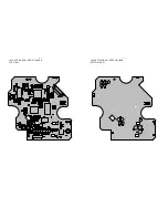
Page 13: ...5 3 5 3 LAYOUT DIAGRAM KEY BOARD TOP VIEW LAYOUT DIAGRAM KEY BOARD BOTTOM VIEW ...

Page 14: ...CAP 2 2µF 80 20 16V Y5V 0805 CAP 0 047µF 10 50V X7R 0603 CAP 680pF 10 16V X7R 0603 IC SC75823E QFP 64 14X14 0 8 SL PCB KB CM420 FR4 1 6mm 171 0X188 2mm GILDING RES 1K 5 1 10W 0805 RES 470 5 1 10W 0805 RES 560 5 1 10W 0805 RES 0 5 1 16W 0603 RES 100 5 1 16W 0603 RES 3K9 5 1 16W 0603 CAP 1µF 80 20 10V Y5V 0603 ENCODER EC11020M2D HA1 013 LED GREEN GM 45GBOW4S Φ3 LXS TACTSW 11 0606 904P 220 70GF 6X6X5...

Page 15: ...6 1 6 1 SERVO BOARD TABLE OF CONTENTS Circuit Diagram 6 2 Layout Diagram 6 3 Electrical Parts List 6 4 ...

Page 16: ...6 2 6 2 CIRCUIT DIAGRAM SERVO BOARD ...

Page 17: ...6 3 6 3 LAYOUT DIAGRAM SERVO BOARD TOP VIEW LAYOUT DIAGRAM SERVO BOARD BOTTOM VIEW ...

Page 18: ... 2N3904 NPN SOT 23 TR MMBT3906LT1 SOT 23 PNP IC SAC4504 28 SSOPH 375B COSMD IC UTC1117 3 3V SOT 23 UTC IC µPD63712 100 LQFP NEC IC SDRAM1MX16 HY57V161610E TSOP11 50 HYNIX IC MLC3190 128 LQFP MCS LOGIC 15PIN 1 0mm FPC SOCKET SMT TYPE TOP CONNECT TYPE RES 68K 5 1 16W 0603 DECK CL C01FY7 SHINWA o E CAP 10µF 20 4X5 5 16V 85 C 1 4 10 23 3 1 1 2 2 8 2 6 1 2 9 1 3 1 1 4 1 2 2 31 1 2 1 2 2 1 1 2 1 7 1 1 1...

Page 19: ...7 1 7 1 MAIN BOARD TABLE OF CONTENTS Circuit Diagram 7 2 Layout Diagram 7 3 to 7 4 Electrical Parts List 7 5 to 7 6 ...

Page 20: ...7 2 7 2 CIRCUIT DIAGRAM MAIN BOARD ...

Page 21: ...7 3 7 3 LAYOUT DIAGRAM MAIN BOARD TOP VIEW ...

Page 22: ...7 4 7 4 LAYOUT DIAGRAM MAIN BOARD BOTTOM VIEW ...

Page 23: ...904 R530 R531 R548 121604000104 121604000123 121604000222 121604000223 121604000272 121604000332 121604000472 121604000473 121604000562 121604000681 121604000682 121604000752 121606000000 121604000000 121608000102 121803000101 121803000102 121803000104 121803000330 121806000224 121806000225 142245000021 142251000001 142245000048 142245000024 142400000386 142400000416 121830000105 121830020106 1218...

Page 24: ...T REC DIODE 1N5401 3A 1V 100V DO 27 HY FUSE ZH270 15A SLOW FUSE TYPE 7PIN CONNECT 2 0mm 90 GBX050 PTC RILAIDA ANTTENA JACK E CAP 470µF 20 8X12 16V 105 E CAP 22µF 20 4X5 16V 105 RCF 2 2 5 1 2W o o C o C 1 1 1 1 1 1 1 1 1 CON402 D802 CON401 ZD805 CON24 C619 C115 R803 7 6 7 6 ELECTRICAL PARTS LIST MAIN BOARD Part No Description QTY Location ...

Page 25: ...8 1 8 1 EXPLODED VIEW MAIN UNIT ...

Page 26: ...ACKET FOR CD420 SCREW FM White Znic M4X6 ASS Y MIAN PCB FOR CD420 BRACKET IC7386 FOR 206 NUT M3 SCREW White Ni PM M3X12 L BRACKET FOR CM420 L FIX BRACKET FOR CD420 SCREW PTS Color Znic M2 0X4 ASS Y SEVRO PCB DECK CL C01FY7 SHINWA DECK BRACKET FOR CM420 SCREW CM M2 6x19 SHINWA CL C01 TOP COVER FOR CD420 LINE BLOCK PVC HEATSINK LABLE FOR CDC SCREW BTB White Znic M2 6X16 SCREW BTS White Ni M2 6X10 PO...

Page 27: ... FOR CD420 SCREW FM White Znic M4X6 ASS Y MIAN PCB FOR CD420 BRACKET IC7386 FOR 206 NUT M3 SCREW White Ni PM M3X12 L BRACKET FOR CM420 L FIX BRACKET FOR CD420 SCREW PTS Color Znic M2 0X4 ASS Y SEVRO PCB DECK CL C01FY7 SHINWA DECK BRACKET FOR CM420 SCREW CM M2 6x19 SHINWA CL C01 TOP COVER FOR CD420 LINE BLOCK PVC HEATSINK LABLE FOR CDC SCREW BTB White Znic M2 6X16 SCREW BTS White Ni M2 6X10 POLE FO...

Reviews: