background image

11

Z390LED

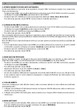
•  Premere il tasto UP e DOWN per selezionare il valore desiderato tra i valori da [

1 - 512

]; tenere premuto 

invece il tasto UP e DOWN per lo scorrimento veloce.

•  Per confermare premere il tasto ENTER.

3.9 INDIRIZZAMENTO DMX

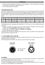
Per poter comandare lo Z390LED con un’unità di comando luce, occorre impostare l’indirizzo di start DMX 

per il primo canale DMX. Se, per esempio, sull’unità di comando è previsto l’indirizzo 33 per comandare la 

funzione del primo canale DMX, si deve impostare sullo Z390LED l’indirizzo di start 33. Le altre funzioni del 

pannello saranno assegnate automaticamente agli indirizzi successivi. Segue un esempio con indirizzo 33 

di start:

Numero 

canali DMX

Indirizzo di 

start (esempio)

Indirizzo DMX 

occupati

Prossimo indirizzo di start 

possibile per unità n°1

Prossimo indirizzo di start 

possibile per unità n°2

Prossimo indirizzo di start 

possibile per unità n°3

9

33

33-41

42

51

60

16

33

33-48

49

65

81

Lo Z390LED dispone di 2 configurazioni di canali DMX a 9 e a 16 canali a cui si può accedere dal pannello 

di controllo.

•  Premere il tasto MENU per accedere alla funzione e attraverso i tasti UP e DOWN scorrere fino a quando 

sul display non appare [

Channel Mode

], quindi premere il tasto ENTER.

•  Premere il tasto UP o DOWN per selezionare [

Mode1(9)

]oppure [

Mode2(16)

].

•  Per confermare premere il tasto ENTER.

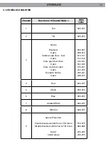
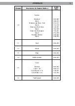
Le tabelle a pagina 13 indicano le modalità di funzionamento e i relativi valori DMX. Come interfaccia DMX, 

l’unità possiede dei contatti XLR a 3 poli.

3.10 COLLEGAMENTI DELLA LINEA DMX

La connessione DMX è realizzata con connettori standard XLR. Utilizzare cavi schermati, 2 poli ritorti, con 

impedenza 120Ω e bassa capacità. 

Per il collegamento fare riferimento allo schema di connessione riportato di seguito:

1

3

2

1

2

3

DMX - OUTPUT

Presa XLR

DMX - INPUT

Spina XLR

Pin1 : Massa - Schermo

Pin2 : - Negativo

Pin3 : + Positivo

ATTENZIONE

La parte schermata del cavo (calza) non deve mai essere collegata alla terra dell’impianto; ciò comportereb-

be malfunzionamenti delle unità e dei controller.

Per passaggi lunghi può essere necessario l’inserimento di un amplificatore DMX.

In tal caso, è sconsigliato utilizzare nei collegamenti cavo bilanciato microfonico poiché non è in grado di 

trasmettere in modo affidabile i dati di controllo DMX. 

Summary of Contents for Z390LED

Page 1: ...I GB Manuale Utente User Manual Z390LED MOVING HEADS ...

Page 2: ...REV 002 12 10 ...

Page 3: ... specifiche tecniche 1 1 Elementi di comando e collegamenti 1 2 Descrizione 1 3 Specifiche tecniche 2 Installazione 2 1 Montaggio 3 Funzioni e impostazioni 3 1 Funzionamento 3 2 Impostazione base 3 3 Struttura del menù 3 4 Funzionamento in modalità automatica 3 5 Comando tramite la musica 3 6 Modalità Master Slave 3 7 Collegamento 3 8 Modalità DMX 3 9 Indirizzamento DMX 3 10 Collegamenti della lin...

Page 4: ...i operazione di manutenzione o pulizia sull unità togliere la tensione dalla rete di alimentazione La temperatura massima raggiungibile sulla superficie esterna dell unità in condizioni di regime termico è di 60 C Assicurarsi che l unità sia spenta e che la temperatura delle parti non possa provocare ustioni La distanza minima tra il proiettore e le pareti circostanti deve essere superiore a 50cm ...

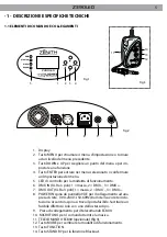
Page 5: ...7 DMX OUT XLR a 3 poli 1 massa 2 DMX 3 DMX 8 POWER IN spina da pannello VDE per il collegamento ad una presa di rete 100 240V 50 60Hz tramite il cavo rete in do tazione Accanto la spina si trova il portafusibile Sostituire un fusibile difettoso solo con uno dello stesso tipo 9 Presa di collegamento per il telecomando EC800 10 MICROFONO per il comando tramite la musica 11 TELECOMANDO EC800 opzional...

Page 6: ...e 25 e 15 opzionale Controllo bilanciamento del bianco per un accurata regolazione della temperatura colore Controllo ed effetti Modalità Master Slave per il controllo sincronizzato di più unità in sequenza Auto Show con 4 sessioni scenografiche preimpostate Attivazione musicale tramite microfono incorporato con regolazione della sensibilità Comando EC800 opzionale per l accesso rapido alle funzio...

Page 7: ... rotazione in senso orario fino all arresto L area di collocazione deve avere una stabilità sufficiente e supportare almeno 10 volte il peso dell unità Inoltre assicurarsi di rispettare tutte le avvertenza in materia di sicurezza È assolutamente necessario assicurare il proiettore contro la caduta utilizzando un cavo di sicurezza in particolare collegare il cavo in un punto adatto in modo che la c...

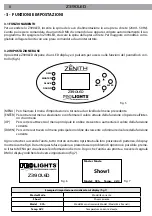
Page 8: ...opzione all inter no di un menu Per scorrere attraverso il menu principale in ordine crescente o aumentare il valore della funzione corrente Per scorrere attraverso il menu principale in ordine decrescente o diminuire il valore della funzione corrente Fig 5 Z390LED MASTER DMX SLAVE SOUND ENTER MENU Ogni volta che si accende l unità tutti i motori verranno ripristinati alla loro posizione di parten...

Page 9: ...ow3 Slave1 Slave2 Mode 1 9 Mode 2 16 Show4 Sound State Off On Sound Sense 0 100 1 512 Black Out No Yes Pan Inverse No Yes Tilt Inverse No Yes Back Light Off On Display Inverse No Yes Auto Test Pan Tilt Red Green Manual Test Blue Amber White Strobe Dimmer 0 255 White Balance Red Green Blue 125 255 Temperature Unit C F ...

Page 10: ...und Sense quindi premere il tasto ENTER Premere il tasto UP o DOWN per selezionare tra i valori da 0 100 Per confermare premere il tasto ENTER 3 6 MODALITÀ MASTER SLAVE Questa modalità consente di collegare in linea più unità Z390LED senza un controller La prima unità sarà impostata come master e le altre funzioneranno come slave Slave Mode con lo stesso effetto Premere il tasto MENU per accedere ...

Page 11: ...dal pannello di controllo Premere il tasto MENU per accedere alla funzione e attraverso i tasti UP e DOWN scorrere fino a quando sul display non appare Channel Mode quindi premere il tasto ENTER Premere il tasto UP o DOWN per selezionare Mode1 9 oppure Mode2 16 Per confermare premere il tasto ENTER Le tabelle a pagina 13 indicano le modalità di funzionamento e i relativi valori DMX Come interfacci...

Page 12: ...erire sull ultima unità una terminazione DMX 3 11 COSTRUZIONE DEL TERMINATORE DMX La terminazione evita la probabilità che il segnale DMX 512 una volta raggiunta la fine della linea stessa venga riflesso indietro lungo il cavo provocando in certe condizioni e lunghezze la sua sovrapposizione al segnale originale e la sua cancellazione La terminazione deve essere effettuata sull ultima unità della ...

Page 13: ...se fast open Open Random Strobe Open 000 007 008 015 016 131 132 139 140 181 182 189 190 231 232 239 240 247 248 255 4 Red 000 255 5 Green 000 255 6 Blue 000 255 7 Amber White 000 255 8 Dimmer 000 255 9 Special Function Enable blackout while Pan or Tilt move Disable blackout while Pan or Tilt move Reset Stand alone 070 079 080 089 200 209 240 255 3 12 TABELLA CANALI DMX ...

Page 14: ...Macro1 Macro2 Macro3 Macro4 Macro5 Macro6 Macro7 Macro8 Macro9 Macro10 Macro11 Macro12 000 015 016 035 036 055 056 075 076 095 096 115 116 135 136 155 156 175 176 195 196 215 216 235 236 255 7 Macro Speed 000 255 8 Special Function Enable blackout while Pan or Tilt move Disable blackout while Pan or Tilt move Reset Stand alone 070 079 080 089 200 209 240 255 9 Dimmer 000 255 ...

Page 15: ...st close Open Slow close fast open Open Random Strobe Open 000 007 008 015 016 131 132 139 140 181 182 189 190 231 232 239 240 247 248 255 11 Red 000 255 12 Green 000 255 13 Blue 000 255 14 White Amber 000 255 15 Color Normal Color 1 32 Color Macro 1 16 Color Fabe 1 16 000 007 008 127 128 191 192 255 16 Fade Speed 000 255 ...

Page 16: ...guenti punti Black Out Modalità Black Out No Disattiva la funzione Yes Attiva la funzione No Disattiva la funzione impost normale Yes Attiva la funzione Rotazione in senso opposto del la testa mobile Pan Inverse Fixture Time Permette di visualizzare le ore di funzionamento del proiettore Reset Permette di eseguire il reset del proiettore Funzione Back Light Back Light Off Disattiva la funzione On ...

Page 17: ...sti UP o DOWN eseguire la calibratura impostando un valore tra 0 255 Premere il tasto ENTER per confermare l impostazione White Balance Questa funzione consente di impostare il bilanciamento del rosso verde e blue Premere il tasto MENU per accedere alla funzione e attraverso i tasti UP e DOWN scorrere fino a quando sul display non appare White Balance Per confermare premere il tasto ENTER Selezion...

Page 18: ... Tenendo premuto il tasto FUNCTION è possibile regolare Pan Position Tilt Position Dimmer Nota La lunghezza del cavo del telecomando è pari a 10 m 4 MANUTENZIONE 4 1 PULIZIA SISTEMA OTTICO E MANUTENZIONE Durante gli interventi assicurarsi che l area sotto il luogo di installazione sia libera da personale non qualificato Spegnere l unità scollegare il cavo di alimentazione ed aspettare finché l uni...

Page 19: ......

Page 20: ......

Page 21: ...ns 1 2 Description 1 3 Technical specifications 2 Installation 2 1 Mounting 3 Functions and settings 3 1 Operation 3 2 Basic 3 3 Menu structure 3 4 Operation in automatic mode 3 5 Music control 3 6 Master Slave Mode 3 7 Linking 3 8 DMX Mode 3 9 DMX addressing 3 10 Connection of the DMX line 3 11 Construction of the DMX termination 3 12 DMX control 3 13 Changing the operating parameters 3 14 Remote...

Page 22: ...er look directly at the light beam Please note that fast changes in lighting e g flashing light may trigger epileptic seizures in photosensitive persons or persons with epilepsy Before starting any maintenance work or cleaning the projector cut off power from the main supply The maximum temperature that can be reached on the external surface of the fitting in a thermally steady state is 60 C Make ...

Page 23: ...1 ground 2 DMX 3 DMX 8 POWER IN mains plug for connection to a socket 100 240V 50 60Hz via the supplied mains cable The support for he mains fuse is located near the mains plug Only replace a blown fuse by one of the same type 9 Connection Jack for the remote control EC800 10 MICROPHONE for music control 11 REMOTE CONTROL EC800 opzional fig 3 12 Button MODE to change operation mode 13 Button FUNCT...

Page 24: ...ion optics Beam angle 25 and 15 optional White balance control for a more accurate colour temperature adjustment Effects and control Master Slave mode for synchronized stand alone operations Auto Show mode with 4 pre programmed show sessions Sound activation by built in microphone with sensitivity adjustment Optional EC800 remote control for easy access to functions and built in shows 0 100 linear...

Page 25: ... place must be of sufficient stability and be able to support a weight of 10 times of the unit s weight Always additionally secure the projector with the safety rope from falling down For this purpose fasten the safety rope at a suitable position so that the maximum fall of the projector will be 20 cm Fig 4 15 Omega kit Beam Diameter mt 0 3 5 7 10 Dist mt Diam mt Lux Center 0 7 1 2 1 8 2 6 3680 14...

Page 26: ...or a more convenient operation it is recommended to connect the unit to a socket which can be switched on and off via a light switch 3 2 BASIC Access control panel functions using the four panel buttons located directly underneath the LED Display fig 5 Every time you turn on the unit it will run built in program to reset all motors to their home position the display will show as fig 6 It will show...

Page 27: ...3 Slave1 Slave2 Mode 1 9 Mode 2 16 Show4 Sound State Off On Sound Sense 0 100 1 512 Black Out No Yes Pan Inverse No Yes Tilt Inverse No Yes Back Light Off On Display Inverse No Yes Auto Test Pan Tilt Red Green Manual Test Blue Amber White Strobe Dimmer 0 255 White Balance Red Green Blue 125 255 Temperature Unit C F ...

Page 28: ...sense will blinking on the display Use UP and DOWN button adjust the sound sensitively from 1 to 100 Press ENTER button to store 3 6 MASTER SLAVE MODE This mode will allow you to link up the units together without a controller Choose a unit to function as the Master The unit must be the first unit in line other units will work as slave Slave Mode with the same effect Select Slave Mode press ENTER ...

Page 29: ...to store The tables on page 13 indicate the operating mode and DMX value The Z390LED is equipped with 3 pole XLR connections 3 10 CONNECTION OF THE DMX LINE DMX connection employs standard XLR connectors Use shielded pair twisted cables with 120Ω impedance and low capacity The following diagram shows the connection mode ATTENTION The screened parts of the cable sleeve must never be connected to th...

Page 30: ...DMX 512 signals being reflected back along the cable when they reaches the end of the line under certain conditions and with certain cable lengths this could cause them to cancel the original signals The termination is prepared by soldering a 120Ω 1 4 W resistor between pins 2 and 3 of the 5 pin male XLR connector as shown in figure ...

Page 31: ... close fast open Open Random Strobe Open 000 007 008 015 016 131 132 139 140 181 182 189 190 231 232 239 240 247 248 255 4 Red 000 255 5 Green 000 255 6 Blue 000 255 7 Amber White 000 255 8 Dimmer 000 255 9 Special Function Enable blackout while Pan or Tilt move Disable blackout while Pan or Tilt move Reset Stand alone 070 079 080 089 200 209 240 255 3 12 DMX CONTROL ...

Page 32: ...Macro1 Macro2 Macro3 Macro4 Macro5 Macro6 Macro7 Macro8 Macro9 Macro10 Macro11 Macro12 000 015 016 035 036 055 056 075 076 095 096 115 116 135 136 155 156 175 176 195 196 215 216 235 236 255 7 Macro Speed 000 255 8 Special Function Enable blackout while Pan or Tilt move Disable blackout while Pan or Tilt move Reset Stand alone 070 079 080 089 200 209 240 255 9 Dimmer 000 255 ...

Page 33: ...st close Open Slow close fast open Open Random Strobe Open 000 007 008 015 016 131 132 139 140 181 182 189 190 231 232 239 240 247 248 255 11 Red 000 255 12 Green 000 255 13 Blue 000 255 14 White Amber 000 255 15 Color Normal Color 1 32 Color Macro 1 16 Color Fabe 1 16 000 007 008 127 128 191 192 255 16 Fade Speed 000 255 ...

Page 34: ...s ENTER button to store The menu shows Black Out Blackout mode No To Disable Yes To Enable No To Disable Yes To Enable Used for reversing Pan move ment Pan Inverse Fixture Time Used for displaying projector op erating hours Reset Used for resetting the projector Back Light function Back Light Off To Disable On To Enable Used for reversing tilt movement Tilt Inverse No To Disable Yes To Enable Disp...

Page 35: ...obe Dimmer Press ENTER button to confirm the selection Use UP and DOWN button to make the adjustment by setting a value between 0 255 Press ENTER button to store White Balance To set the custom balance of red green and blue Select White Balance press ENTER button to confirm Use UP and DOWN button to select the color you wish to regulate Red Green Blue Press ENTER button to confirm the selection Us...

Page 36: ...t Position Dimmer Note The length of the cable remote EC800 is 10 m 4 MAINTENANCE 4 1 CLEANING THE UNIT AND MAINTENANCE Make sure the area below the installation place is free from unwanted persons during setup Switch off the unit unplug the main cable and wait until the unit has cooled down All screws used for installing the device and any of its parts should be tightly fastened and should not be...

Page 37: ......

Page 38: ......

Page 39: ...chi conseguenti sono a carico del possessore dell apparecchio A tutti gli effetti la validità della garanzia è avallata unicamente dalla presentazione del certificato di garanzia The guarantee covers the unit in compliance with existing regulations You can find the full version of the General Guarantee Conditions on our web site www musiclights it Abstract General Guarantee Conditions Please remem...

Page 40: ...date Data acquisto FORM TO BE FILLED IN AND MAILED CEDOLA DA COMPILARE E SPEDIRE FORM TO BE FILLED IN AND KEPT CEDOLA DA COMPILARE E CONSERVARE PROV ZIP CODE C A P MODEL MODELLO SERIAL N SERIE N Purchased by Acquistato da SURNAME COGNOME Dealer s stamp and signature Timbro e firma del Rivenditore NAME NOME ADDRESS VIA N CITY CITTA Purchasing date Data acquisto PROV ZIP CODE C A P ...

Page 41: ......

Page 42: ......

Page 43: ......

Page 44: ... Music Lights S r l PROLIGHTS is a brand of Music Lights S r l company Via Appia Km 136 200 04020 Itri LT ITALY tel 39 0771 72190 fax 39 0771 721955 www musiclights it info musiclights it Music Lights S r l entertainment technologies ISO 9001 2008 Certified Company ...

Reviews: