background image

7

SUNPIX 24TRI

- 3 -  FUNCTIONS  AND SETTINGS

3.1 OPERATION

Connect the supplied main cable to a socket (100-240 VAC-50/60 Hz). Then the unit is ready for operation 

and can be operated via a DMX controller or it independently performs its show program in succession. 

To switch off, disconnect the mains plug from the socket. For a more convenient operation it is recom-

mended to connect the unit to a socket which can be switched on and off via a light switch.


3.2 BASIC

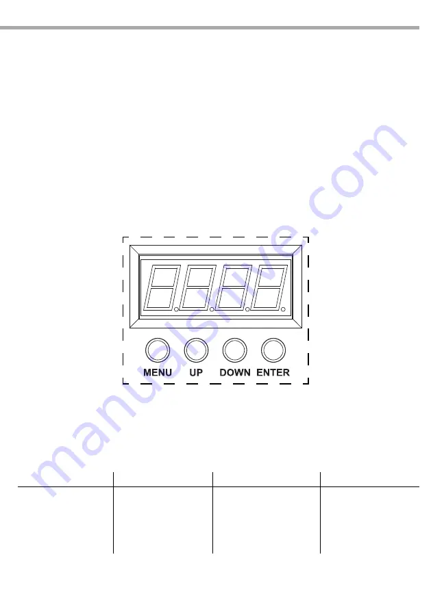
Access control panel functions using the four panel buttons located directly underneath the LED Display 

(fig.3).

MENU

UP

DOWN

ENTER

Navigates through the 
menu list or to return a 
previous menu option

Used to change the mode 
of operation and increases 
the numeric value when in 
a function

Used to change the mode 
of operation and decreases 
the numeric value when in a 
function

Used to select and store the 
current menu or confirm the 
current function value or 
option within a menu

Fig.3

Summary of Contents for SUNPIX24TRI

Page 1: ...EN IT Manuale Utente User Manual SUNPIX24TRI SUPER SLIM LED PAR ...

Page 2: ...ate nel presente manuale di istruzioni Tutte le revisioni e gli aggiornamenti sono disponibili nella sezione Manuali sul sito www musiclights it All rights reserved by Music Lights S r l No part of this instruction manual may be reproduced in any form or by any means for any commercial use In order to improve the quality of products Music Lights S r l reserves the right to modify the characteristi...

Page 3: ...ontaggio 3 Funzioni e impostazioni 3 1 Funzionamento 3 2 Impostazione base 3 3 Struttura menu 3 4 Modalità automatica 3 5 Preset color 3 6 Modalità static color 3 7 Modalità Master Slave 3 8 Collegamento 3 9 Modalità DMX 3 10 Indirizzamento DMX 3 11 Funzione dimmer 3 12 Collegamenti della linea DMX 3 13 Costruzione del terminatore DMX 3 14 Tabella canali DMX 4 Manutenzione 4 1 Manutenzione e puliz...

Page 4: ...getti metallici Non smontare e non apportare modifiche all unità Tutti gli interventi devono essere sempre e solo effettuati da personale tecnico qualificato Rivolgersi al più vicino centro di assistenza tecnica autorizzato Se si desidera eliminare il dispositivo definitivamente consegnarlo per lo smaltimento ad un istituzione locale per il riciclaggio Attenzioni e precauzioni per l installazione ...

Page 5: ... delle Condizioni Generali di Garanzia Si prega dopo l acquisto di procedere alla registrazione del prodotto sul sito www musiclights it In alternativa il prodotto può essere registrato compilando e inviando il modulo riportato alla fine del manuale A tutti gli effetti la validità della garanzia è avallata unicamente dalla presentazione del certificato di garanzia Music Lights constata tramite ve ...

Page 6: ...r 16 milioni di colori Durata media diodi LED 50 000 ore Funzionamento ed elettronica Pannello di controllo tramite display LED 4 caratteri Diverse configurazioni DMX disponibili 3 9 12 72 canali per controllo professionale o semplificato 3 canali RGB 9 canali Dimmer RGB macro strobe auto speed dimmer curve 12 canali RGB quadrant cont 72 canali 24x RGB Regolazione curva dimmer 5 configurazioni sel...

Page 7: ... 2 DMX 3 DMX 5 POWER OUT output alimentazione per connessioni di più unità in serie 6 POWER IN spina da pannello VDE per il collegamento ad una presa di rete 100 240V 50 60Hz tramite il cavo di rete in dotazione Sotto la spina si trova il portafusibile Sostituire un fusibile difettoso solo con uno dello stesso tipo 7 MICROFONO per il comando tramite musica 8 REGOLATORE SENSIBILITÀ AUDIO nella moda...

Page 8: ...lità sufficiente e supportare almeno 10 volte il peso dell unità Inoltre assicurarsi di rispettare tutte le avvertenze in materia di sicurezza Fissare il proiettore attraverso l apposita staffa 1 ad una collocazione idonea È assolutamente necessario assicurare il proiettore contro la caduta utilizzando un cavo di sicurezza in particolare collegare il cavo in un punto adatto in modo che la caduta d...

Page 9: ...are l unità con una presa comandata da un interruttore 3 2 IMPOSTAZIONE BASE Il proiettore SUNPIX24TRI dispone di un LED display e 4 pulsanti per accesso alle funzioni del pannello di controllo fig 3 Fig 3 MENU UP DOWN ENTER Per scorrere il menu principale o tornare ad una opzione del menu precedente Per scorrere attraverso le diverse funzioni o aumentare il valore della funzione stessa Per scorre...

Page 10: ...C 04 Cyan C 05 Magenta C 06 Yellow C 07 White Auto Program P P 1 Fade transition Red Green Blue Yellow Purple Cyan White 0 100 0 P 2 Fade transition Red Green Blue Yellow Purple Cyan White 0 100 P 3 Fade transition Red Green Blue Yellow Purple Cyan White 100 0 P 4 Auto fade transition color randomly P 5 Loop of P1 P4 P 6 Auto Colors chasing P 7 Auto color chasing and strobe by sound active S000 S1...

Page 11: ...ENTER per confermare Attraverso i tasti UP DOWN selezionare il colore desiderato Premere il tasto ENTER Utilizzare i tasti UP DOWN per impostare il valore desiderato 001 100 Premere il tasto ENTER per continuare e passare al successivo colore R G b Utilizzare i tasti UP DOWN per selezionare il valore desiderato 001 100 Continuare fino ad ottenere la miscelazione del colore Premere ENTER per salvar...

Page 12: ...3 Le altre funzioni del pannello saranno assegnate automaticamente agli indirizzi successivi Segue un esempio con indirizzo 33 di start Numero canali DMX Indirizzo di start esempio Indirizzo DMX occupati Prossimo indirizzo di start possibile per unità n 1 Prossimo indirizzo di start possibile per unità n 2 Prossimo indirizzo di start possibile per unità n 3 3 33 33 35 36 39 42 9 33 33 41 42 51 60 ...

Page 13: ...Collegare quindi l uscita DMX con l ingresso DMX della successiva unità l uscita di quest ultima con l ingresso di quella successiva e via dicendo finchè tutte le unità sono collegate formando una catena Per installazioni in cui il cavo di segnale deve percorrere lunghe distanze è consigliato inserire sull ulti ma unità una terminazione DMX 3 13 COSTRUZIONE DEL TERMINATORE DMX La terminazione evit...

Page 14: ...e 1 RED 0 100 000 255 2 GREEN 0 100 000 255 3 BLUE 0 100 000 255 CH Function in CH5 mode Value 1 RED 0 100 000 255 2 GREEN 0 100 000 255 3 BLUE 0 100 000 255 4 DIMMER 0 100 000 255 5 COLOR MACROS No function Sound control 7colors On Strobe increasing 000 001 005 006 010 011 255 ...

Page 15: ...alue 1 DIMMER 0 100 000 255 2 RED 0 100 000 255 3 GREEN 0 100 000 255 4 BLUE 0 100 000 255 5 COLOR MACROS No function Red 100 Green0 100 Blue 0 Red 100 0 Green 100 Blue 0 Red 0 Green 100 Blue 0 100 Red 0 Green 100 0 Blue 100 Red 0 100 Green 0 Blue 100 Red 100 Green 0 Blue 100 0 Red 100 Green up Blue 0 100 Red 0 100 Green 100 0 Blue 100 Red 100 Green 100 Blue 100 White 1 3200K White 2 3400K White 3...

Page 16: ...0 000 255 3 DIMMER BLUE 0 100 000 255 II 4 DIMMER RED 0 100 000 255 5 DIMMER GREEN 0 100 000 255 6 DIMMER BLUE 0 100 000 255 III 7 DIMMER RED 0 100 000 255 8 DIMMER GREEN 0 100 000 255 9 DIMMER BLUE 0 100 000 255 IV 10 DIMMER RED 0 100 000 255 11 DIMMER GREEN 0 100 000 255 12 DIMMER BLUE 0 100 000 255 II III IV I ...

Page 17: ...ction in CH72 mode Value LED1 1 DIMMER RED 0 100 000 255 2 DIMMER GREEN 0 100 000 255 3 DIMMER BLUE 0 100 000 255 LED2 4 DIMMER RED 0 100 000 255 5 DIMMER GREEN 0 100 000 255 6 DIMMER BLUE 0 100 000 255 LED24 10 DIMMER RED 0 100 000 255 11 DIMMER GREEN 0 100 000 255 12 DIMMER BLUE 0 100 000 255 ...

Page 18: ...igliamo che la pulizia interna sia eseguita da personale qualificato 4 2 RISOLUZIONE DEI PROBLEMI Anomalie Possibili cause Controlli e rimedi Il proiettore non illumina Mancanza di alimentazione di rete Dimmer impostato a 0 Tutti i colori impostati a 0 LED difettoso i Scheda LED difettosa Verificarelapresenzadellatensionealimentazione Incrementare i valori del canale dimmer Incrementare i valori d...

Page 19: ......

Page 20: ......

Page 21: ...d connections 2 Installation 2 1 Mounting 3 Functions and settings 3 1 Operation 3 2 Basic 3 3 Menu structure 3 4 Automatic 3 5 Static color 3 6 Custom static color 3 7 Master Slave mode 3 8 Linking 3 9 DMX operation 3 10 DMX addressing 3 11 Dimmer 3 12 Connection of the DMX line 3 13 Construction of the DMX termination 3 14 DMX control 4 Maintenance 4 1 Maintenance and cleaning the unit 4 2 Troub...

Page 22: ...t dismantle or modify the fixture All work must always be carried out by qualified technical personnel Contact the nearest sales point for an inspection or contact the manufacturer directly If the unit is to be put out of operation definitively take it to a local recycling plant for a disposal which is not harmful to the environment Warnings and installation precautions If this device will be oper...

Page 23: ...ite www musiclights it Please remember to register the piece of equipment soon after you purchase it logging on www musiclights it The product can be also registered filling in and sending the form available on your guarantee certificate For all purposes the va lidity of the guarantee is endorsed solely on presentation of the guarantee certificate Music Lights will verify the validity of the claim...

Page 24: ...mixing 16 million colours LEDs average life span 50 000 hours Electronics and features User panel through 4Char LED display Several DMX selectable configurations 3 9 12 72 channels for advanced or basic controlling 3 channels RGB 9 channels Dimmer RGB macro strobe auto speed dimmer curve 12 channels RGB quadrant cont 72 channels 24x RGB Dimmer curve setting 5 selectable configurations Auto mode bu...

Page 25: ...or the mains fuse is located near the mains plug Only replace a blown fuse by one of the same type 7 MICROPHONE to control the show by the external audio signal 8 CONTROL SENSITIVITY for the sensitivity of response in case of music control via the internal microphone 9 CONTROL PANEL with display and 4 button used to access the control panel functions and manage them MENU UP DOWN ENTER MIC SENSITIV...

Page 26: ... comply scrupulously with all the regulations particularly re garding safety currently in force in the country in which the fixture s being used Install the projector at a suitable location by means of the mounting bracket 1 Always additionally secure the projector with the safety rope from falling down For this purpose fas ten the safety rope at a suitable position so that the maximum fall of the...

Page 27: ...nnect the unit to a socket which can be switched on and off via a light switch 3 2 BASIC Access control panel functions using the four panel buttons located directly underneath the LED Display fig 3 MENU UP DOWN ENTER Navigates through the menu list or to return a previous menu option Used to change the mode of operation and increases the numeric value when in a function Used to change the mode of...

Page 28: ...nta C 06 Yellow C 07 White Auto Program P P 1 Fade transition Red Green Blue Yellow Purple Cyan White 0 100 0 P 2 Fade transition Red Green Blue Yellow Purple Cyan White 0 100 P 3 Fade transition Red Green Blue Yellow Purple Cyan White 100 0 P 4 Auto fade transition color randomly P 5 Loop of P1 P4 P 6 Auto Colors chasing P 7 Auto color chasing and strobe by sound active S000 S100 Run speed Custom...

Page 29: ...red color Press ENTER button Using UP DOWN button select the desired color value 001 100 By selecting 000 the color will remain off Press ENTER button to continue to the next color R G b Using UP DOWN button select the desired color value 001 100 Continue until the desired mix is obtained The order of colors is red green and blue Press ENTER button to continue to the strobe setting Using UP DOWN b...

Page 30: ...e controller is provided for controlling the function of the first DMX channel adjust the start address 33 on the SUNPIX24TRI The other functions of the light effect panel are then automatically assigned to the following addresses An example with the start address 33 is shown below DMX Address 33 DMX Address 60 DMX Address 42 DMX Address 51 Example 9 DMX channels configuration 9CH mode Fig 4 DMX51...

Page 31: ...f the first unit Connect the DMX output to the DMX input of the following unit Connect again the output to the input of the following unit until all the units are connected in chain When the signal cable has to run longer distance is recommended to insert a DMX termination on the last unit DMX OUTPUT XLR socket DMX INPUT XLR plug Pin1 GND Shield Pin2 Negative Pin3 Positive Fig 5 3 13 CONSTRUCTION ...

Page 32: ... function Red 100 Green0 100 Blue 0 Red 100 0 Green 100 Blue 0 Red 0 Green 100 Blue 0 100 Red 0 Green 100 0 Blue 100 Red 0 100 Green 0 Blue 100 Red 100 Green 0 Blue 100 0 Red 100 Green up Blue 0 100 Red 0 100 Green 100 0 Blue 100 Red 100 Green 100 Blue 100 White 1 3200K White 2 3400K White 3 4200K White 4 4900K White 5 5600K White 6 5900K 000 010 011 030 031 050 051 070 071 090 091 110 111 130 131...

Page 33: ...ixelprogram6 Pixelprogram7 Pixelprogram8 Pixelprogram9 Pixelprogram10 Pixelprogram11 Pixelprogram12 Pixelprogram13 Pixelprogram14 Pixelprogram15 Pixelprogram16 Pixelprogram17 Randompixelprogram Pixelprogramscroll1 17 Pixelprogramscrolltosound1 17 000 009 010 019 020 029 030 039 040 049 050 059 060 069 070 079 080 089 090 099 100 109 110 119 120 129 130 139 140 149 150 159 160 169 170 179 180 189 1...

Page 34: ...0 000 255 3 DIMMER BLUE 0 100 000 255 II 4 DIMMER RED 0 100 000 255 5 DIMMER GREEN 0 100 000 255 6 DIMMER BLUE 0 100 000 255 III 7 DIMMER RED 0 100 000 255 8 DIMMER GREEN 0 100 000 255 9 DIMMER BLUE 0 100 000 255 IV 10 DIMMER RED 0 100 000 255 11 DIMMER GREEN 0 100 000 255 12 DIMMER BLUE 0 100 000 255 II III IV I ...

Page 35: ...ction in CH72 mode Value LED1 1 DIMMER RED 0 100 000 255 2 DIMMER GREEN 0 100 000 255 3 DIMMER BLUE 0 100 000 255 LED2 4 DIMMER RED 0 100 000 255 5 DIMMER GREEN 0 100 000 255 6 DIMMER BLUE 0 100 000 255 LED24 10 DIMMER RED 0 100 000 255 11 DIMMER GREEN 0 100 000 255 12 DIMMER BLUE 0 100 000 255 ...

Page 36: ...a soft clean cloth Never use a liquid it might penetrate the unit and cause damage to it Warning we strongly recommend internal cleaning to be carried out by qualified personnel 4 2 TROUBLESHOOTING Problems Possible causes Checks and remedies Fixture does not light up No mains supply Dimmer fader set to 0 All color faders set to 0 Faulty LED Faulty LED board Check the power supply voltage Increase...

Page 37: ...chi conseguenti sono a carico del possessore dell apparecchio A tutti gli effetti la validità della garanzia è avallata unicamente dalla presentazione del certificato di garanzia The guarantee covers the unit in compliance with existing regulations You can find the full version of the General Guarantee Conditions on our web site www musiclights it Abstract General Guarantee Conditions Please remem...

Page 38: ...date Data acquisto FORM TO BE FILLED IN AND MAILED CEDOLA DA COMPILARE E SPEDIRE FORM TO BE FILLED IN AND KEPT CEDOLA DA COMPILARE E CONSERVARE PROV ZIP CODE C A P MODEL MODELLO SERIAL N SERIE N Purchased by Acquistato da SURNAME COGNOME Dealer s stamp and signature Timbro e firma del Rivenditore NAME NOME ADDRESS VIA N CITY CITTà Purchasing date Data acquisto PROV ZIP CODE C A P ...

Page 39: ......

Page 40: ...39 0771 721955 www musiclights it info musiclights it Music Lights S r l entertainment technologies ISO 9001 2008 Certified Company 2013 Music Lights S r l PROLIGHTS è un brand di proprietà della Music Lights S r l PROLIGHTS is a brand of Music Lights S r l company ...

Reviews: