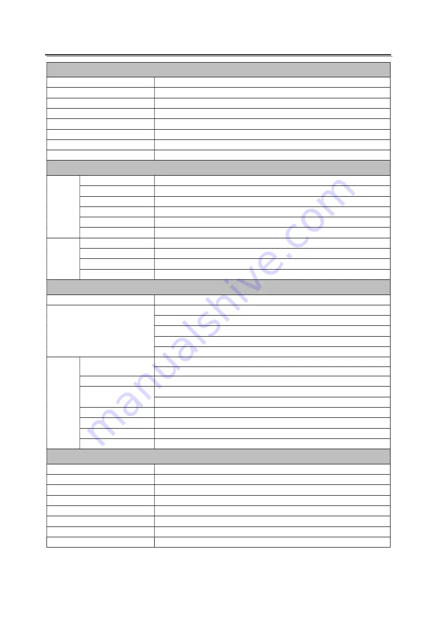
ProHD DT-X93Hx2 User Manual Download Page 17

17 


Specification 

LCD Performance


Size 

9 inches ×2 

Display area 

191.5×119.7 mm 

Resolution 

1920×1200 

Color 

8 bit 

Aspect ratio 

16:9 / 4:3 

Brightness 

450 cd/m

2


Contrast 

1000:1 

Viewing Angle 

Horizontal: 170°      Vertical: 170° 

Input/output – Each LCD 

Input 

BNC×2 

2K/3G/HD/SD-SDI ×2 

BNC×1 

CVBS input 

HDMI×1 

HDMI input 

GPI×1 

UMD, GPI control input 

USB×1 

For firmware upgarde 

3.5mm×1 

analog audio input 

Output


BNC×2


2K/3G/HD/SD-SDI loop through output ×2 

BNC×1 

CVBS loop through output 

HDMI×1


HDMI loop through output 

3.5mm×1


SDI/HDMI/analog audio output 

Video Format


CVBS 

NTSC / PAL 

HDMI 

480i / 576i / 480p / 576p 

1080i

60 / 59.94 / 50


720p

60 / 59.94 / 50


1080p

60 / 59.94 / 50 / 30 / 29.97 / 25 / 24 / 23.98


1080psf

30 / 29.97 / 25 / 24 / 23.98


SDI 

SMPTE-2048-2 

2048

×

1080p

23.98 / 24 / 25 / 29.97 / 30 / 50 / 59.94 / 60


2048

×

1080i

50 / 59.94 / 60


SMPTE-425M-A/B  1080p

60 / 59.94 / 50


SMPTE-274M 

1080i

60 / 59.94 / 50


1080p

30 / 29.97 / 25 / 24 / 23.98


SMPTE-RP211 

1080psf

30 / 29.97 / 25 / 24 / 23.98


SMPTE-296M 

720p

60 / 59.94 / 50


SMPTE-125M 

480i

59.94


ITU-R BT.656 

576i

50


General 

Input voltage 

DC 6.5V-24V 

Power consumption 

36W 

Working temperature 

0°C

+40°C 

Working humidity 

10%

90% 

Storage temperature 

15°C

~﹢

60°C 

Storage humidity 

10%

90% 

Dimensions 

484

×

177

×

112.8mm 

Net weight (main body) 

2.8 kg 


Summary of Contents for DT-X93Hx2

Page 1: ...1 Model DT X93Hx2 9 x2 FHD Rack Mount LCD Monitor User Manual Ver A Please read this User Manual throughout before using ...

Page 2: ...uct described in this manual without prior notice 4 The warranty period of this product is 2 years and does not cover the following 1 Physical damage to the surface of the products including scratches cracks or other damage to the LCD screen or other externally exposed parts 2 The LCD dot defects are not over three 3 Any damage caused by using third party power adaptors 4 Any damage or breakdown c...

Page 3: ...se disconnect the power cable under the following situations A If you do not operate this monitor for a period of time B If the power cable or power adaptor is damaged C If the monitor housing is broken The monitor 1 Please don t touch the screen with your fingers which would probably deface the screen 2 Please don t press the screen the LCD is extremely exquisite and flimsy 3 Please don t lay thi...

Page 4: ...4 Contents Preface 2 Maintenance 3 Contents 4 Installation Dimension 5 Operation Instructions 6 Front Panel 6 OSD 7 Back Panel 9 Sub Menu 11 Specification 17 Trouble shooting 18 ...

Page 5: ...5 Installation Dimension The main body in mm ...

Page 6: ...s display DISPLAY Press DISPLAY to turn on or turn off relevant status information Rotary Knob BRIGHT 0 100 value adjustment and the default value is 50 CONTRAST 0 100 value adjustment and the default value is 50 SATURATION 0 100 value adjustment and the default value is 50 MENU ENTER When the menu is inactivated presses MENU ENTE to turn on the main menu Revolve MENU ENTER to adjust settings or p...

Page 7: ... Set up the UMD under UMD submenu AFD SDI User can set function keys F1 F5 or GPI pins as AFD to turn on or off this function If no relevant information is detected it will be displayed as AFD UNLOCKED Audio Monitor the audio information The relevant parameters like position audio channels and blending etc can be changed under Audio submenu User can set function Keys F1 F5 or GPI pins as Audio to ...

Page 8: ...age is over exposed or not by showing black and white lines on the monitor It is considered over exposed when luminance value exceeds 90 User can set function Keys F1 F5 or GPI pins as Zebra to turn on or off this function Freeze Frame The freeze frame is to capture and display the current broadcast frame User can set function Keys F1 F5 or GPI pins as Freeze Frame to turn on or off this function ...

Page 9: ... IN HDMI input HDMI A HDMI OUT HDMI loop through output from HDMI IN HDMI A AUDIO IN 3 5mm analog audio input AUDIO OUT 3 5mm audio output SDI HDMI embedded audio and analog audio output DC IN Connect with 4 pin XLR power adapter support 6 5V 24V voltage input Pin 1 Negative Pin 4 Positive CVBS IN CVBS input BNC SDI IN2 SDI input BNC SDI IN1 SDI input BNC USB User firmware upgrade socket AC DC Pow...

Page 10: ...h needed to adjust press MENU ENTER the selected item and its parameters will be highlighted in yellow 4 Revolve MENU ENTER to change the selected item s parameter press MENU ENTER to apply and save the settings 5 Revolve MENU ENTER to select Exit press MENU ENTER to quit submenu Select Exit Status under the Main Menu and press to quit Main Menu Notice The items in gray cannot be set up If there i...

Page 11: ...own below 1 Display the current video signal and format 2 Display the current function keys setup 2 Picture To adjust picture parameters 3 Color Temp To select different color temperature or setup user defined color parameters Only Color Temp is set to User the Red Blue Green Gain or Red Blue Green Bias can be adjusted ...

Page 12: ...y Yellow Tally Aspect Ratio Scan Mode Zoom Mode Mute Freeze Frame Flip Color Temp Time Code Zebra Audio Bar False Color AFD H V Delay R G B Mono Marker Color Bar UMD Audio Alarm Focus Assist When connecting the GPI pin with ground the setted function will be turned on and goes out when disconnecting Example 1 Under GPI submenu set GPI control to On set 2 Pin to Red Tally when the pin 2 of the exte...

Page 13: ...the screen UMD setup Connect the external control equipment Set Display Type to UMD Set address Baud Rate and Parity Adjust the external control equipment and send UMD command the monitor will display as User can set the character and color of the UMD and the color of Tally1 and Tally2 Please see 5 GPI to check the RS485 pin sequence and definition User can set the character and color of the UMD a...

Page 14: ... of the area inside the scales marker Example 8 Audio 1 When Bar Frame is set to Off only the audio meter will be displayed When Bar Frame is set to On frame and real time audio value will be displayed 2 When Audio Alarm is set to On if no embedded audio is detected the audio bar will display UNLOCKED If the audio value is too low the audio bar will display MUTE 3 Select Channel Under SDI signal u...

Page 15: ...DMI CVBS For example if channel is selected to SDI2 SDI IN2 has no input and CVBS has input When turn on the monitor after automatic inspection SDI2 has no recognized signal and CVBS has recognized signal then the input signal will be CVBS When set to No update model will not be supported 2 Logo When powered on the screen will display ProHD logo ...

Page 16: ... monitor will upgrade automatically and will restart when upgrade finished Enter Menu System Update Kernel select YES and the monitor will upgrade automatically and will restart when upgrade finished Please DO NOT cut off power during firmware upgrade 11 OSD 12 Key Inhibit If the Key Inhibit is On there is no response when all the buttons expert MENU ENTER are pressed the sreen will be displayed a...

Page 17: ...t 3 5mm 1 SDI HDMI analog audio output Video Format CVBS NTSC PAL HDMI 480i 576i 480p 576p 1080i 60 59 94 50 720p 60 59 94 50 1080p 60 59 94 50 30 29 97 25 24 23 98 1080psf 30 29 97 25 24 23 98 SDI SMPTE 2048 2 2048 1080p 23 98 24 25 29 97 30 50 59 94 60 2048 1080i 50 59 94 60 SMPTE 425M A B 1080p 60 59 94 50 SMPTE 274M 1080i 60 59 94 50 1080p 30 29 97 25 24 23 98 SMPTE RP211 1080psf 30 29 97 25 2...

Page 18: ... Bad contact of BNC or HDMI cable Change cable Video signal has Interference Remove the interference source s Improper adjustment of the color parameters Adjust the Recall profile to Default under System submenu Distortion of the image Reset the Aspect ratio Set to Red Green Blue only or Mono Turn the Blue only Red Only Green Only Mono off under R G B Mono submenu Turn on the Focus Assist function...

Page 19: ...LC and distributed in North America by JVCKENWOOD USA Corporation To obtain service or for further information please contact SWIT Electronics USA LLC Address 3350 Scott Blvd 61 02 Santa Clara CA 95054 Toll free 1 866 986 SWIT 7948 Tel 408 260 8258 Fax 408 228 8438 Email info swit us Website www swit us ...

Reviews: