


20
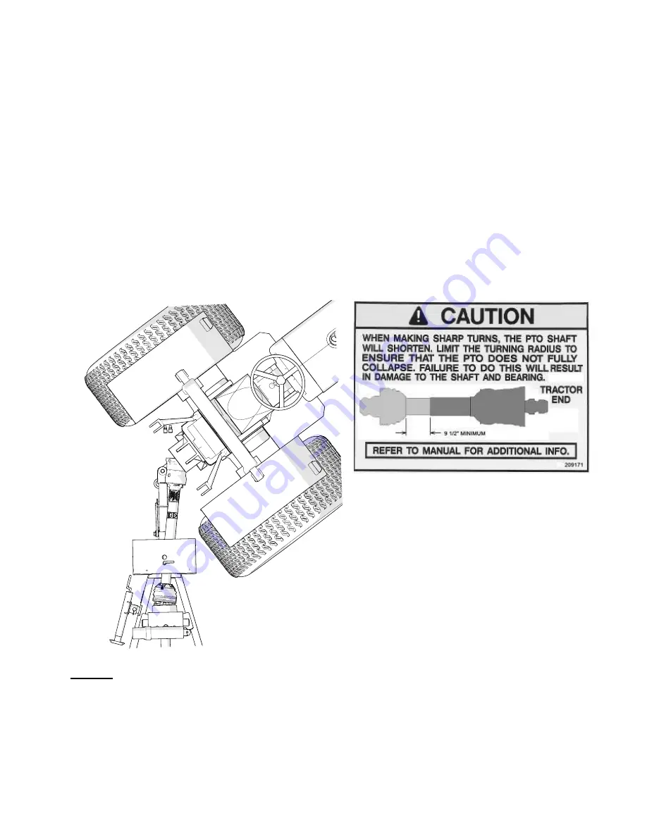
CHECK PTO LENGTH DURING TURNS
:
The Pro-Flex 120 mower features a hose support which also serves the function to
limit the steering angle of the mower without damage to components. In proper
operation, the tractor tire should contact the hose support first if the operator attempts
to turn too sharp without damage to the drive-line.
To check tire contact:
a)
With the tractor in the lowest gear and travelling very slowly, make a sharp turn.
b)
As you turn, watch closely to make sure the tractor tires contact the hose
support. (not other parts of the mower)
c)
If the tires do not contact the hose support, adjust tractor tire width (if possible),
so they contact the hose support. Contact us for a modified guard
.
NOTE:
This is not the worst condition. Making turns while the tractor is angling up a
hill will cause the PTO shaft to collapse even more. The operator should avoid making
sharp turns on uneven ground.
Summary of Contents for TDR-12
Page 2: ......
Page 4: ......
Page 6: ...3 ...
Page 38: ...35 ...
Page 46: ...TDR 12 15 Parts Manual 4 1 3 Deck Assembly TDR 15 Wing Rear All 02 2017 ...
Page 47: ...TDR 12 15 Parts Manual 5 1 4 Wing Deck Assembly TDR 12 02 2017 ...
Page 49: ...TDR 12 15 Parts Manual 7 1 6 Gearbox Assembly 02 2015 ...
Page 50: ...TDR 12 15 Parts Manual 8 2 FRAME ASSEMBLY 2 1 Frame Assembly 04 2016 ...
Page 51: ...TDR 12 15 Parts Manual 9 2 2 Lift Assembly 02 2015 ...
Page 56: ...TDR 12 15 Parts Manual 14 2 7 Wheel Assemblies 07 2014 ...
Page 57: ...TDR 12 15 Parts Manual 15 3 HYDRAULICS 3 1 Hydraulics 02 2015 ...
Page 58: ...TDR 12 15 Parts Manual 16 4 DRIVELINE 4 1 Driveline 06 2015 ...
Page 61: ...TDR 12 15 Parts Manual 19 4 4 Intermediate PTO Shaft 07 2014 ...
Page 64: ...TDR 12 15 Parts Manual 22 4 7 Rear Deck PTO Shaft 09 2014 ...
Page 65: ...TDR 12 15 Parts Manual 23 4 8 4 Way Gearbox 07 2014 ...
Page 66: ...TDR 12 15 Parts Manual 24 4 9 Deck Gearbox Standard Rotation 02 2015 ...
Page 67: ...TDR 12 15 Parts Manual 25 4 10 Deck Gearbox Reverse Rotation 02 2015 ...


