


6
3.4. ENCLOSED INFORMATION FOR THE
INSTALLATION OF OPTIONS
3.4.1. LATCH OPTION
The low consumption of the equipment (0.12
watts/hour), and its latch electrovalves, make this
option suitable for those installation which work with
battery. It is not indispensable, but a small solar
panel can be mounted to avoid the manual loading
of the battery.
LATCH ELECTROVALVES WITH TWO CABLES.
This electrovalve model works reversing the
polarity between the two cables, to activate or
deactivate it.
One of the cables is to be connected to the
outlet common “C” and the other one to the
corresponding outlet.
If the electrovalve does the opposite of what the
programmer has ordered it to do, it would be
necessary to reverse the cables that are connected
to the common and outlet.
LATCH ELECTROVALVES WITH THREE CABLES.
This models have a bridge in the right superior
part of the base card to change the working voltages
to the outputs (see indicative stick). Without the
bridge the outputs are working to 12 Vdc and with
the bridge installed they will have a voltage near to
24 volts. From the company the units are delivered
with the bridge connected. The voltage depends on
the type of solenoids, by this, it can be changed
depending on your needs.
Also it is included for this version a diode box,
to which two of the three cables, the red and the
black one, belonging to each solenoid have to be
connected. The red one will be connected to the
group of terminals linked to the red cable which goes
to the programmer (start common). The black one
will be connected to the other group of terminals
(stop common).
The order of the sector numbers is not taken
into account in the terminals of the diode box.
The other cable, normally white, will be
connected to the programmer, to the outlet
corresponding to its sector or to the “M” general
valve outlet.
In the built-in model, the black cable of the
diode box has to be connected to the “CE” input
common terminal and the battery negative has to be
used as input common.
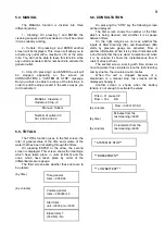
Example of connection:
Summary of Contents for Agronic
Page 10: ...10 R 910 1...


