background image

14

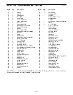
PART LISTÑModel No. 831.288281

R0198A

Key No. Qty.

Description

1

1

Frame

2

1

Upright

3

1

Seat Frame

4

1

Handlebar

5

2

Pulse Grip

6

1

Left Side Shield 

7

1

Right Side Shield 

8

1

Console 

9

1

Resistance Knob

10

1

Resistance Cable/Control 

11

4

M5 x 30mm Screw

12

4

M5 Nut

13

1

Reed Switch/Wire

14

4

M6 x 25mm Hex Head Screw

15

1

Backrest

16

1

Seat

17

2

Seat Handle

18

4

M6 x 38mm Button Head Bolt

19

2

Foam Handle Grip

20

1

1Ó x 3Ó Endcap

21

8

Tree Fastener

22

21

#8 x 5/8Ó Screw

23

2

#8 x 3/8Ó Screw

24

8

M6 x 16mm Hex Head Screw

25

3

M10 x 25mm Button Head Screw

26

3

M10 Split Washer

27

2

Pedal Strap

28

1

Right Pedal

29

1

Crank/Pulley

30

1

Notched Bearing Nut

31

2

Bearing

32

2

Bearing Cup

33

1

Slotted Bearing Nut

34

1

Crank Washer

35

1

Crank Nut

36

2

M8 Flanged Hex Nut

37

2

M6 Eyebolt

38

2

Adjustment Bracket

39

4

M6 Nut

Key No. Qty.

Description

40

2

M10 Washer

41

2

Extension Wire

42

1

Flywheel

43

1

10mm x 13mm Spacer

44

1

Flywheel Axle

45

1

Left Pedal

46

2

M10 x 52mm Button Head Screw

47

2

Wheel

48

5

2Ó x 3Ó Endcap

49

1

1 1/2Ó x 3Ó Endcap

50

1

Cable Clamp

51

1

M6 x 56mm Bolt

52

1

Large Flat Washer

53

4

#8 Flat Washer

54

1

Clamp Bolt

55

1

Clamp Nut

56

1

Resistance Hook

57

1

Resistance Spring

58

1

Magnet Bracket

59

1

M8 x 65mm Hex Head Bolt

60

1

M8 Nylon Locknut

61

1

Drive Belt

62

2

1 1/4Ó Round Endcap

63

1

2Ó x 4Ó Endcap

64

1

Frame Bushing

65

1

Seat Frame Bushing

66

4

M6 Nylon Locknut

67

4

M6 Split Washer

68

1

Lock Knob

69

1

Seat Bracket

70

4

M10 x 105mm Button Head Bolt

71

4

M10 Flat Washer

72

4

M10 Nylon Locknut

73

2

M8 Split Washer

74

4

Rubber Bumper

75

1

M4 x 16mm Screw

#

1

UserÕs Manual

#

1

4mm Allen Wrench

#

1

5.5mm Allen Wrench

Note: Ò#Ó indicates a non-illustrated part. Specifications are subject to change without notice. See the back cover
of this manual for information about ordering replacement parts.

Summary of Contents for 831.288281

Page 1: ...281 Serial No The serial number can be found in the location shown below Write the serial number in the space above CAUTION Read all precautions and instruc tions in this manual before using this equipment Save this manual for future reference Serial Number Decal Patent Pending ...

Page 2: ... than 250 pounds 7 Wear appropriate clothing when exercising do not wear loose clothing that could become caught on the 975s Always wear athletic shoes when using the 975s 8 Always keep your back straight when using the 975s Do not arch your back 9 If you feel pain or dizziness at any time while exercising stop immediately and begin cooling down 10 The 975s is intended for in home use only Do not ...

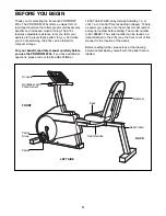
Page 3: ...FORM 975s If you have additional questions please call our toll free HELPLINE at 1 800 736 6879 Monday through Saturday 7 a m until 7 p m Central Time excluding holidays To help us assist you please note the product model number and serial number before calling The model number is 831 288281 The serial number can be found on a decal attached to the 975s see the front cover of this manual for the l...

Page 4: ...wing refers to the key number of the part The second number refers to the quantity used in assembly Note Some small parts may have been pre attached for shipping If a part is not in the parts bag check to see of it has been pre assembled M10 Split Washer 26 Ð3 M10 x 25mm Button Head Screw 25 Ð3 8 x 5 8Ó Screw 22 Ð4 M6 x 38mm Button Head Bolt 18 Ð4 M6 x 16mm Hex Head Screw 24 Ð8 M10 Flat Washer 71 ...

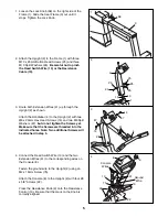
Page 5: ...Head Screws 14 and two M6 Split Washers 67 but do not tighten the Screws yet Make sure that the Screws are threaded into the indicated holes Note Two additional Screws will be attached in step 5 2 2 26 26 25 25 25 1 10 13 3 41 2 14 67 67 14 4 4 Connect the Reed Switch Wire 13 and the two Extension Wires 41 to the corresponding wires on the Console 8 Fasten the ground wire to the Upright 2 using an...

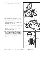
Page 6: ...0 x 105mm Button Head Bolts 70 four M10 Flat Washers 71 and four M10 Nylon Locknuts 72 7 Attach the Seat 16 to the Seat Bracket 69 with four M6 x 16mm Hex Head Screws 24 71 71 69 69 3 72 70 24 16 14 67 67 14 2 4 5 6 7 8 Attach a Seat Handle 17 to the Seat Bracket 69 with two M6 x 38mm Button Head Bolts 18 and two M6 Nylon Locknuts 66 Attach the other Seat Handle 17 to the Seat Bracket 69 in the sa...

Page 7: ... 45 to the desired position Press the Pedal Strap onto the adjustment tab on the Left Pedal Adjust the Pedal Strap on the Right Pedal not shown in the same manner 15 24 69 29 27 45 Tab 9 10 11 The Console 8 requires two ÒAAÓ batteries not included Ñalkaline batteries are recommended Open the battery cover not shown on the back of the Console Press two batteries into the battery clip Make sure that...

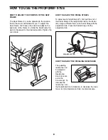
Page 8: ... TO ADJUST THE PEDAL STRAPS To adjust each Pedal Strap 27 first pull the end of the Pedal Strap off the adjustment tab on the Pedal 45 Align a different hole in the Pedal Strap with the adjustment tab Press the Pedal Strap onto the adjustment tab HOW TO ADJUST THE PEDALING RESISTANCE The pedaling resistance can be adjusted with the Resistance Knob 9 locat ed on the Console 8 To increase the resist...

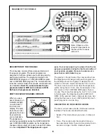
Page 9: ...rtant The target pace is a goal pace Your actual pace may be slower than the tar get pace especially during the first few months of your exercise program Be sure to exercise at a pace that is comfortable for you The graphs on the left side of the console show how the target pace will change during each program see the drawing above Each graph is divided into ten columns and each column represents ...

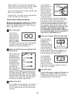
Page 10: ...anual mode one indicator on the inner P A C E R track will light As you exer cise this indicator will move around the quarter mile track If you selected a pacer program two indicators on the P A C E R track will light The indicator on the inner track will show your actual pace The indicator on the outer track will move around the track at the programmed pace As you exercise adjust your pace so tha...

Page 11: ... heart rate will not be shown If an ÒLÓ appears in the PULSE display then the pulse sensor received too little pulse information to accurately calculate your pulse Let go of the metal contacts then place your hands on the contacts again Your palms must be resting on the inner con tacts and your fingers must be touching the outer contacts If an ÒHÓ appears in the PULSE display then the pulse sensor...

Page 12: ...of the Crank Place the end of a standard screw driver in one of the slots in the Slotted Bearing Nut 33 Lightly tap the screwdriver with a hammer to turn the Slotted Bearing Nut counterclockwise until the arms are no longer loose Do not overtighten the Slotted Bearing Nut When the Slotted Bearing Nut is properly tightened tighten the Crank Nut HOW TO STORE THE PROFORM 975S When the PRO FORM 975s i...

Page 13: ...hen you stop exercising If your heart rate is too high decrease the intensity of your exercise If your heart rate is too low increase the intensity of your exercise WORKOUT GUIDELINES A well rounded workout includes the following three phases A warm up phase lasting 5 to 10 minutes Begin with slow controlled stretches and progress to more rhyth mic stretches This will increase the body temperature...

Page 14: ... 39 4 M6 Nut Key No Qty Description 40 2 M10 Washer 41 2 Extension Wire 42 1 Flywheel 43 1 10mm x 13mm Spacer 44 1 Flywheel Axle 45 1 Left Pedal 46 2 M10 x 52mm Button Head Screw 47 2 Wheel 48 5 2Ó x 3Ó Endcap 49 1 1 1 2Ó x 3Ó Endcap 50 1 Cable Clamp 51 1 M6 x 56mm Bolt 52 1 Large Flat Washer 53 4 8 Flat Washer 54 1 Clamp Bolt 55 1 Clamp Nut 56 1 Resistance Hook 57 1 Resistance Spring 58 1 Magnet ...

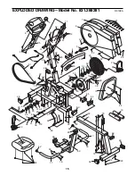
Page 15: ... 22 50 1 51 39 54 56 53 55 40 39 38 37 36 23 23 65 64 15 24 20 62 19 22 22 3 66 66 18 49 18 62 58 57 59 63 60 44 43 39 38 37 36 35 34 33 31 32 47 46 27 29 46 47 48 61 16 17 24 48 48 6 7 2 17 42 68 70 71 72 69 10 13 73 73 67 67 52 22 74 22 74 48 75 EXPLODED DRAWINGÑModel No 831 288281 R0198A 15 ...

Page 16: ...ice Center To request service or to order parts by telephone call the toll free numbers listed at the left When requesting help or service or ordering parts please be pre pared to provide the following information The MODEL NUMBER of the product 831 288281 The NAME of the product PROFORM 975s The KEY NUMBER and DESCRIPTION of the PART see the PART LIST and the EXPLODED DRAWING on pages 14 and 15 F...

Reviews: