background image

6

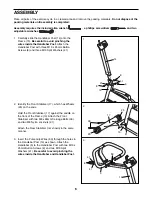
2. Identify the Front Stabilizer (17), which has Wheels

(25) on the ends.

Hold the Front Stabilizer (17) against the saddle on
the front of the Frame (15). Attach the Front
Stabilizer with two M8 x 90mm Carriage Bolts (30)
and two M8 Nylon Locknuts (21).

Attach the Rear Stabilizer (not shown) in the same
manner.

1. Carefully slide the Handlebar Post (14) onto the

Frame (15). 

Be careful to avoid pinching the

wires inside the Handlebar Post. 

Attach the

Handlebar Post with three M10 x 25mm Button
Screws (8) and three M10 Split Washers (41).

1

2

17

25

25

15

30

21

14

8

8

8

41

15

41

14

41

41

60

8

3

5

3. Insert the Pulse Grip Wires (60) through the holes in

the Handlebar Post (14) as shown. Attach the
Handlebar (5) to the Handlebar Post with two M10 x
25mm Button Screws (8) and two M10 Split
Washers (41). 

Be careful to avoid pinching the

wires inside the Handlebar and Handlebar Post.

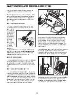
ASSEMBLY

Place all parts of the exercise cycle in a cleared area and remove the packing materials. 

Do not dispose of the

packing materials until assembly is completed.

Assembly requires the included allen wrench                    , a phillips screwdriver                       and two
adjustable wrenches                     . 

Summary of Contents for 831.288070

Page 1: ...stomer satisfaction If you have questions or if there are missing or damaged parts we will guarantee complete satis faction through direct assis tance from our factory TO AVOID UNNECESSARY DELAYS PLEASE CALL DIRECT TO OUR TOLL FREE CUSTOMER HOT LINE The trained techni cians on our customer hot line will provide immediate assis tance free of charge to you CUSTOMER HOT LINE 1 800 999 3756 Mon ÐFri 6...

Page 2: ...UTIONS 3 BEFORE YOU BEGIN 4 PART IDENTIFICATION CHART 5 ASSEMBLY 6 HOW TO USE THE EXERCISE CYCLE 8 CONDITIONING GUIDELINES 10 MAINTENANCE AND TROUBLE SHOOTING 12 PART LIST 14 EXPLODED DRAWING 15 HOW TO ORDER REPLACEMENT PARTS Back Cover ...

Page 3: ...do not wear loose clothing that could become caught on the exercise cycle Always wear athletic shoes for foot protection 8 When adjusting the seat insert the seat knob through one of the holes in the seat post see the drawing on page 4 Do not insert the seat knob under the seat post 9 Always keep your back straight when using the exercise cycle Do not arch your back 10 If you feel pain or dizzines...

Page 4: ... 3756 Monday through Friday 6 a m until 6 p m Mountain Time excluding holidays To help us assist you please mention the product model number and serial number when calling The model number is 831 288070 The serial number can be found on a decal attached to the 940s see the front cover of this manual for the location of the decal Before reading further please look at the drawing below and familiari...

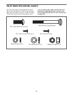
Page 5: ...ART IDENTIFICATION CHART Use the chart below for help identifying the small parts used in assembly The number in parenthesis below each part refers to the key number of the part The second number refers to the quantity used in assembly Note Some parts may have been pre attached for shipping purposes If a part is not found in the parts bag check to see if it has been pre attached ...

Page 6: ...ree M10 x 25mm Button Screws 8 and three M10 Split Washers 41 1 2 17 25 25 15 30 21 14 8 8 8 41 15 41 14 41 41 60 8 3 5 3 Insert the Pulse Grip Wires 60 through the holes in the Handlebar Post 14 as shown Attach the Handlebar 5 to the Handlebar Post with two M10 x 25mm Button Screws 8 and two M10 Split Washers 41 Be careful to avoid pinching the wires inside the Handlebar and Handlebar Post ASSEMB...

Page 7: ...Connect the Reed Switch Wire 50 and the two Pulse Grip Wires 60 to the corresponding wires on the Console 7 If your Console has a ground wire attach it to the Handlebar Post 14 with an M4 x 16mm Screw 9 Attach the Console 7 to the Handlebar Post 14 with four M4 x 12mm Console Screws 4 Next press the Resistance Knob 10 onto the Resistance Control 11 Be sure that the mark on the Knob is correctly al...

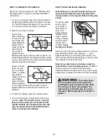
Page 8: ... decrease the resis tance turn the Resistance Knob counterclockwise BATTERY INSTALLATION Before the console can be operated two ÒAAÓ batteries must be installed If you have not installed batteries see assembly step 4 on page 7 DESCRIPTION OF THE CONSOLE The innovative console features six modes that pro vide instant exercise feedback during your workouts The modes are described below SpeedÑDisplay...

Page 9: ...edals are not moved and the monitor buttons are not pressed for four min utes the power will turn off automatically in order to conserve the batteries HOW TO USE THE PULSE SENSOR Note Before you can use the pulse sensor you must peel the protective vinyl covering off the metal contacts on the top and bottom of the pulse sensor To use the pulse sensor place your hands on the metal con tacts Your pa...

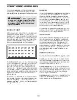
Page 10: ...ew minutes of exercise does your body begin to use stored fat calories for energy If your goal is to burn fat adjust the intensity of your exercise until your heart rate is near the lowest num ber in your training zone as you exercise For maximum fat burning adjust the intensity of your exercise until your heart rate is near the middle num ber in your training zone as you exercise Aerobic Exercise...

Page 11: ...straight and your back foot flat on the floor Bend your front leg lean forward and move your hips toward the wall Hold for 15 counts then relax Repeat 3 times for each leg To cause further stretching of the achilles tendons bend your back leg as well Stretches Calves achilles tendons and ankles 4 Quadriceps Stretch With one hand against a wall for balance reach back and grasp one foot with your ot...

Page 12: ...ch wire HOW TO ADJUST THE REED SWITCH If the console does not display correct feedback the reed switch should be adjusted In order to adjust the reed switch the Left Side Shield 1 must be removed refer to the drawing at the top of this page Using an adjustable wrench turn the Left Pedal 28 clockwise and remove it from the Crank 33 Remove the two M4 x 16mm Screws 9 and three M4 x 38mm Self tapping ...

Page 13: ... it Remove the right side shield Press down on the center of the Belt 16 between the front and rear sprockets There should be from 1 4Ó to 3 4Ó of vertical movement in the center of the Belt If the Belt 16 is properly adjusted reattach the side shields and pedals If the Belt needs to be adjusted loosen the M8 Washer Nut 37 on each side of the Flywheel 32 To tighten the Belt turn the two M6 Stop nu...

Page 14: ... 2 Wheel 26 2 Wheel Spacer 27 2 M6 x 16mm Self tapping Screw 28 1 Left Pedal 29 1 Seat Knob 30 4 M8 x 90mm Carriage Bolt 31 1 M10 Flat Washer 32 1 Flywheel 33 1 Crank Pulley 34 3 M4 x 38mm Self tapping Screw 35 1 Flywheel Spacer 36 1 Flywheel Axle 37 2 M8 Washer Nut 38 2 M6 Eye Bolt 39 2 Adjustment Bracket 40 1 Side Shield Cover 41 7 M10 Split Washer 42 1 Bearing Assembly 43 1 ÒCÓ Magnet Spring 44...

Page 15: ... 20 9 22 23 29 24 25 26 27 15 16 24 25 26 27 21 38 58 51 39 28 33 13 33 30 50 9 21 21 21 48 32 46 37 43 59 53 30 18 44 44 36 35 41 45 17 41 41 41 40 42 55 9 52 42 37 41 47 38 39 47 47 34 34 54 56 57 31 8 41 60 50 9 EXPLODED DRAWINGÑModel No 831 288070 R0200A 15 ...

Page 16: ...tend to any product or damage to a product caused by or attributable to freight damage abuse mis use improper or abnormal usage or repairs not provided by an ICON authorized service center products used for commercial or rental purposes or products used as store display models No other warranty beyond that specifically set forth above is authorized by ICON ICON is not responsible or liable for ind...

Reviews: