background image

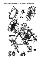
PART LIST—Model No. PETL62010

R0601A

1

1

Motor Belt

2

1

Pulley/Flywheel/Fan

3

4

Motor Nut

4*

1

Motor/Pulley/
Flywheel/Fan

5

1

Incline Motor Bolt

6

2

Plastic Incline Motor
Spacer

7

1

Incline Motor

8

1

Stop Bracket

9

1

Small Nut

10

1

Star Washer

11

1

Latch Assembly

12

1

Frame

13

1

Optic Switch Bolt

14

2

Interface Bracket

15

8

Incline Motor Nut

16

6

Hood Screw

17

2

Plastic Stand-off

18

1

Hood Bracket (Short)

19

1

Hood Bracket (Long)

20

2

Warning Decal

21

1

Reed Switch

22

1

Reed Switch Clip

23

1

Motor/Controller Wire

24

1

Controller

25

1

Electronics Bracket

26

1

Circuit Breaker

27

1

Receptacle

28

2

Extension Leg Assm.

29

1

On/Off Switch

30

1

Inlet Bracket

31

1

Incline Leg

32

2

Frame Pivot Bolt

33

2

Frame Pivot Spacer

34

1

Upright Wire Harness

35

1

Front Roller Adj. Bolt

36

3

Roller Adj. Washer

37

3

Motor Tension Nut/ 
Front Roller Nut

38

4

Motor Bolt

39

2

Cap Screw

40

1

Left Foot Rail Cap

41

2

Foot Rail

42

1

Front Roller/Pulley

43

1

Magnet

44

2

Platform Screw

45

2

Isolator

46

8

Isolator Screw

47

15

Plastic Fastener

48

1

Shield

49

1

Belt Guide

50

1

Book Holder

51

1

Front Belly Pan

52

1

Power Supply

53

2

Cable Tie Clamp

54

4

Cable Tie

55

1

Walking Belt

56

1

Splitter

57

1

Rear Roller

58

1

Belly Pan Spacer

59

2

Rear Foot

60

1

Rear Foot Screw

61

1

Ground Wire

62

8

Ground Wire Screw

63

1

Belly Pan

64

1

Rear Endcap

65

2

Rear Roller Adj. Bolt

66

1

Motor

67

1

Latch Decal

68

4

Rear Platform Screw

69

4

Electronics Screw

70

1

Catch

71

1

Walking Platform

72

5

8” Cable Tie

73

1

Jack

74

1

Motor Tension Bolt

75

2

Foot Rail Insert

76

5

Screw

77

1

Console

78

1

Motor Isolator Plate

79

4

Long Screw

80

1

10’ iFIT.com Wire

81

4

Motor Bushing

82

1

Upright

83

2

Incline Leg Pivot Bolt

84

2

Side Hood Screw

85

2

Handrail Extension

86

2

Wheel Bolt

87

1

Console Base

88

1

Motor Tension Washer

89

12

Console/Catch Screw

90

1

Key/Clip

91

1

Incline Motor Plate

92

1

Right Foot Rail Cap

93

1

Motor Tension Bushing

94

1

Motor Hood

95

2

Front Wheel

96

1

Incline Motor Shield

97

2

Base Pad

98

1

12” Audio Wire

99

2

Upright Grommet

100

1

Allen Wrench

101

23

Short Screw

102 

2

Euro Power Cord

103

2

Extension Leg

104

2

Extension Leg Cap

105

1

Shock

106

1

Choke

107

2

Pulse Bar Bolt

108

2

Pulse Bar Washer

109

1

Pulse Bar

110

1

Left Handgrip

111

1

Right Handgrip

112

1

Audio Wire Nut

113

4

Thick Base Pad

114**

1

Chest Pulse Sensor 
Strap

115**

1

Chest Pulse Sensor

116

1

Console Base Bottom

117

2

Upright Endcap

118 1

Motor 

Sleeve

119

8

Hood Bracket Screw/
Incline Shield Screw

120

1

Rear Foot Spacer 

121**

1

Hand Weight Set

122

1

Long Incline Motor Bolt

123

2

Static Warning

124

1

Hand Pulse Wire

125

1

Motor/Choke Bracket

126

1

Filter

127

1

Trim Guard

128**

1

iFIT.com CD

129**

1

iFIT.com Videocassette

#

1

8” White Wire, 2F

#

1

10” White Wire, 2F

#

1

14” White Wire, 2F

#

1

4” Black Wire, 2F

#

1

8” Black Wire, M/F

#

1

4” Blue Wire, 2F

#

1

8” Blue Wire, 2F

#

1

10” Blue Wire, 2F

#

1

14” Blue Wire, 2F

#

1

6” Green Wire, F/Ring

#

1

7” Green Wire, M/Ring

#

1

8” Green Wire, F/Ring

#

1

8” Green Wire, 2 Ring

#

1

25” Wire Harness

#

1

User's Manual

* Includes all parts shown in the 

box

**For more information about the op-

tional hand weight set, chest pulse
sensor, or iFIT.com CD or video-
cassette, see page 18

# These parts are not illustrated 

Key 

No.

Qty.

Description

Key 

No.

Qty.

Description

Key 

No.

Qty.

Description

To locate the parts listed below, refer to the EXPLODED DRAWING attached in the centre of this manual.

23

Summary of Contents for 620

Page 1: ...in the location shown below Write the serial number in the space above for reference www proform com Visit our website at Class HC Fitness Product QUESTIONS As a manufacturer we are committed to providing complete customer satisfaction If you have questions or if there are missing parts please call Or write ICON Health Fitness Ltd Unit 4 Revie Road Industrial Estate Revie Road Beeston Leeds LS11 8...

Page 2: ...readmill on any surface that blocks air openings To protect the floor or carpet from damage place a mat under the treadmill 4 When choosing a location for the treadmill make sure that the location and position per mit access to a plug 5 Keep the treadmill indoors away from mois ture and dust Do not put the treadmill in a garage or covered patio or near water 6 Do not operate the treadmill where ae...

Page 3: ...ill by placing objects under the treadmill 21 When folding or moving the treadmill make sure that the latch pin is fully inserted into the catch see page 19 22 Inspect and tighten all parts of the treadmill regularly 23 When using iFIT com CD s and videos an electronic chirping sound will alert you when the speed and or incline of the treadmill is about to change Always listen for the chirp and be...

Page 4: ...hown at 20 of actual size The decals shown below have been placed on your treadmill If a decal is missing or illegible please call our Customer Service Department to order a free replacement decal see the front cover of this manual Apply the decal in the location shown ...

Page 5: ... our Customer Service Department at 08457 089009 To help us assist you please note the product model number and serial num ber before calling The model number of the treadmill is PETL62010 The serial number can be found on a decal attached to the treadmill see the front cover of this manual for the location Before reading further please review the drawing below and familiarise yourself with the pa...

Page 6: ... 103 into the treadmill as shown Make sure that the Extension Leg is turned so the Thick Base Pad 113 is on the bottom Next tip the treadmill to the other side and insert the other Extension Leg not shown in the same way Lower the side of the treadmill so that both Extension Legs 103 are resting flat on the floor 2 With the help of a second person carefully lower the treadmill frame and then tip t...

Page 7: ... 59 and the Rear Foot Spacer 120 from the treadmill Reattach the right Rear Foot without the Rear Foot Spacer Hold the treadmill with both hands and lower the treadmill as described on page 19 Check the left Rear Foot 59 see drawing 6a If the left Rear Foot is still off the floor raise the treadmill and re move the left Rear Foot Snap the Rear Foot Spacer 120 onto the left Rear Foot and reattach t...

Page 8: ... of the power cord into the socket on the treadmill Refer to drawing 2 Plug the power cord into an appropriate outlet that is prop erly installed and earthed in accordance with all local codes and ordinances Note In Italy an adaptor not included must be used between the power cord and the outlet Important The treadmill is not compatible with GFCI equipped outlets Use only a power cord type H05VV F...

Page 9: ...iFIT com CD pro grams but add the excitement of working out with a class and an instructor the hottest new trend at health clubs With the treadmill connected to your computer you can also go to our new internet site at www iFIT com and access even more programs Choose from a se lection of basic programs that interactively control the speed and incline of your treadmill to help you achieve your per...

Page 10: ...g the Speed buttons To stop the walking belt press the Stop button The Time Incline Seg Time display will begin to flash To restart the walking belt press the Start button or the Speed button Change the incline of the treadmill as desired To change the incline of the treadmill press the Incline buttons Each time one of the buttons is pressed the incline will change by 0 5 The in cline range is 1 5...

Page 11: ... selected remove and then reinsert the key Note To reset the displays press the Stop button remove the key and then reinsert the key Measure your heart rate if desired Stand on the foot rails and place your hands on the metal contacts on the pulse bar Avoid moving your hands When your pulse is de tected the heart shaped indicator in the Cals Watts Pulse dis play will flash steadily and a series of...

Page 12: ... onds remain in the first segment a series of tones will sound and the treadmill will automatically ad just to the speed and incline settings for the second segment The program will continue in this way until the Time Incline Seg Time display counts down to zero The walking belt will then slow to a stop If the speed or incline setting for the current seg ment is too high or too low you can manuall...

Page 13: ...r end of the cable into the splitter Plug the split ter into the PHONES jack on your CD player Plug your headphones into the other side of the splitter HOW TO CONNECT YOUR PORTABLE STEREO Note If your stereo has an RCA type AUDIO OUT jack see instruction A below If your stereo has a 3 5 mm LINE OUT jack see instruction B If your stereo has only a PHONES jack see instruction C A Plug one end of the...

Page 14: ...used side of the RCA adap tor Plug the RCA adaptor into the LINE OUT jack on your stereo HOW TO CONNECT YOUR COMPUTER Note If your computer has a 3 5mm LINE OUT jack see instruction A If your computer has only a PHONES jack see instruction B A Plug one end of the audio cable into the jack on the front of the treadmill near the power cord Plug the other end of the cable into the LINE OUT jack on yo...

Page 15: ...ote To purchase iFIT com CD s or to pur chase iFIT com videocassettes call 08457 089009 Make sure that the on off switch near the power cord is in the on position In addition make sure that the power cord is properly plugged in see HOW TO PLUG IN THE POWER CORD on page 8 When you are ready to begin exercising step onto the foot rails of the treadmill Find the clip attached to the key see the drawi...

Page 16: ...o move at 1 mph When the next chirp is heard the speed and incline will change to the next settings of the CD or video program The program can also be stopped by pressing the Stop button on your CD player or VCR When the CD or video program is completed the walking belt will stop and the Time Incline Seg Time display will begin to flash Note To use an other CD or video program press the Stop butto...

Page 17: ...When you start the program an on screen count down will begin Return to the treadmill and stand on the foot rails Find the clip attached to the key and slide the clip onto the waistband of your clothing When the on screen countdown ends the program will begin and the walking belt will begin to move Hold the handrails step onto the walking belt and begin walking During the program an electronic chi...

Page 18: ...ge the unit of measure ment IMPORTANT The Cals Watts Pulse display should be blank If a d ap pears in the display the con sole is in the demo mode This mode is intended to be used only when a treadmill is displayed in a store When the console is in the demo mode the power cord can be plugged in the key can be removed from the console and the displays and in dicators on the console will automatical...

Page 19: ...direct sunlight Do not leave the treadmill in the stor age position in temperatures above 30 C 85 F HOW TO MOVE THE TREADMILL Before moving the treadmill convert the treadmill to the stor age position as described above Make sure that the latch pin is fully inserted into the catch 1 Hold the handrails as shown and place one foot against a wheel 2 Tilt the treadmill back until it rolls freely on th...

Page 20: ... Check the circuit breaker located on the treadmill frame near the power cord see c above If the circuit breaker has tripped wait for five minutes and then press the switch back in b Make sure that the power cord is plugged in c Unplug the power cord wait for five minutes and then plug the power cord back in d Remove the key from the console Reinsert the key fully into the console e Make sure that...

Page 21: ...ing belt is centred b If the walking belt has shifted to the right first re move the key and UNPLUG THE POWER CORD Using the allen wrench turn the left rear roller adjust ment bolt counterclockwise and the right bolt clock wise 1 4 of a turn each Be careful not to overtighten the walking belt Plug in the power cord insert the key and run the treadmill for a few minutes Repeat until the walking bel...

Page 22: ...ctivity that requires large amounts of oxygen for prolonged periods of time This increases the demand on the heart to pump blood to the muscles and on the lungs to oxygenate the blood For aerobic exercise adjust the speed and incline of the treadmill until your heart rate is near the highest number in your training zone WORKOUT GUIDELINES Each workout should include the following three parts A War...

Page 23: ...r Isolator Plate 79 4 Long Screw 80 1 10 iFIT com Wire 81 4 Motor Bushing 82 1 Upright 83 2 Incline Leg Pivot Bolt 84 2 Side Hood Screw 85 2 Handrail Extension 86 2 Wheel Bolt 87 1 Console Base 88 1 Motor Tension Washer 89 12 Console Catch Screw 90 1 Key Clip 91 1 Incline Motor Plate 92 1 Right Foot Rail Cap 93 1 Motor Tension Bushing 94 1 Motor Hood 95 2 Front Wheel 96 1 Incline Motor Shield 97 2...

Page 24: ...rope com When ordering parts please be prepared to give the following information The MODEL NUMBER OF THE PRODUCT PETL62010 The NAME OF THE PRODUCT PROFORM 620 treadmill The SERIAL NUMBER OF THE PRODUCT see the front cover of this manual The KEY NUMBER OF THE PART S see the PART LIST on page 23 and the EXPLODED DRAWING attached in the centre of this manual The DESCRIPTION OF THE PART S see the PAR...

Page 25: ...15 31 38 39 15 15 76 18 119 22 21 3 1 3 4 2 39 40 92 33 43 42 32 68 44 45 46 41 71 55 68 44 101 101 47 45 46 47 47 62 53 54 59 60 62 61 64 65 101 59 47 63 57 67 51 66 36 65 36 68 68 12 75 75 37 74 37 81 98 93 88 101 101 120 37 25 69 48 58 27 62 126 78 118 102 112 EXPLODED DRAWING Model No PETL62010 R0601A ...

Page 26: ...8 107 109 87 77 89 89 46 46 116 50 117 117 89 20 127 Ki rk Ni eb er ga ll P R O D U C T LI T G R O U P 119 113 101 96 113 101 83 82 84 16 84 94 101 91 99 13 72 76 105 76 16 34 56 23 80 73 20 108 107 46 46 90 121 79 79 124 123 123 97 97 115 114 14 10 9 128 114 129 EXPLODED DRAWING Model No PETL62010 R0601A ...

Reviews: