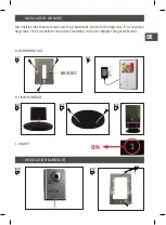
Determine the position of the camera outside at the door. The
ideal installation height is 155 to 165 cm. Then smaller and larger
persons remain in picture. Install the camera in such a way that
direct sunlight is avoided. This results in poor image quality.
Connect the wiring according to diagram below. We again emphasise that the power
supply wiring may not be extended or cut through: this causes the appliance to work
poorly and invalidates the warranty.
If a door lock is to be connected, its connection must be from the outside camera as
shown on the diagram above. The lock may consume no more than 300 mA and must
have a memory function (the lock remains in position “free” until just before the door is
pushed open). The order for connecting these wires is equal.
INSTALLATION CAMERA (2)
1
2
2
5
7
8
12-15V
12-15V
1
2
3 4
5 6 7 8
MATCHING
Summary of Contents for PAC120
Page 3: ...SCHEMA 1 2 2 5 7 8 12 15V 12 15V 1 2 3 4 5 6 7 8 MATCHING 200689002_PAC120_IM januari 2016 NL...
Page 15: ...SCHEMA 1 2 2 5 7 8 12 15V 12 15V 1 2 3 4 5 6 7 8 MATCHING 200689002_PAC120_IM januari 2016 FR...
Page 27: ...SCHEMA 1 2 2 5 7 8 12 15V 12 15V 1 2 3 4 5 6 7 8 MATCHING 200689002_PAC120_IM januari 2016 DE...
Page 39: ...SCHEMA 1 2 2 5 7 8 12 15V 12 15V 1 2 3 4 5 6 7 8 MATCHING 200689002_PAC120_IM januari 2016 UK...

