Proceq ZAA 2600.SW Instruction Manual Download Page 36


Page 36 

7.6.5 Lubrication the guide rods 


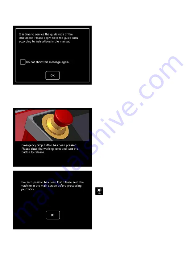
After a service performance of about 
2’000 km a message will appear at 
start-up reminding you to lubricate the 
guide rods. Carry out the lubrication as 
described in chapter 11.3 

“Lubrication 

of the guide rods

” on page 48. 

To switch off the reminder until the next 
interval, 

choose “Do not show this 

message again” and close with “OK”. 


7.7 Emergency stop function  

Pressing the Emergency Stop button (11) immediately stops the motor. The power 
supply of the motor is interrupted so that the tool holder (4) can be moved by hand.  

The touch screen and control unit of 
the Proceq ZAA 2600 remain active 
since only the power supply is 
interrupted. 
 
To unlock the Emergency Stop button 
(11), turn it counterclockwise.  
 
The following message will be 
displayed after unlocking the 
Emergency Stop (11): 


The Zero position must be reset. Move 
the tool holder (4) to the desired 
starting position and press the „Zero”

 button. 


Summary of Contents for ZAA 2600.SW

Page 1: ...Proceq ZAA 2600 SW Automatic Scrub Tester Instruction Manual ...

Page 2: ......

Page 3: ...ptions for crockmeter tests 12 4 Device overview 14 5 Assembly and starting up 16 5 1 Assembly 16 5 2 Startup 17 5 3 Shutdown 18 5 4 Glass plate 18 5 5 Disassembly for transport 18 6 Scrub test 19 6 1 Preparation 19 6 1 1 Available friction sets 19 6 1 2 Use of the friction sets 20 6 2 Carry out a scrub test 23 7 Operation and Menu 27 7 1 Main screen 27 7 1 1 Manual moving 27 7 1 2 Zero the scrub ...

Page 4: ...6 3 Cycle speed and stroke length cannot be set 34 7 6 4 The motor is overheated 35 7 6 5 Lubrication the guide rods 36 7 7 Emergency stop function 36 8 Crocking with the scrub tester 37 8 1 Preparation 37 8 2 Mounting the friction finger sets 37 8 2 1 Mounting the friction finger set A 38 8 2 2 Mounting the friction finger set B 39 8 2 3 Mounting the friction finger set C 40 8 3 Carry out crockme...

Page 5: ... resulting from technical progress modified construction or similar are reserved without obligation for Proceq SA to update Some of the images shown in this instruction manual may be of a pre production model and or are computer generated therefore the design features of the delivered product differ in various aspects The instruction manual has been drafted with the utmost care Nevertheless errors...

Page 6: ...ing time Upgrade can be achieved at any time by simply purchasing an add on kit Fast tool change friction sets and friction finger sets for crocking tests Scalability ensures upgrade possibility after initial purchase without returning the equipment Up to 4 wet and or dry tests can be carried out at the same time Customised tests can be carried out easily with the optional universal holder Storage...

Page 7: ...operation Always wear safety glasses during operation Only connect the Proceq ZAA 2600 to alternating current of a voltage of 100 240 V at 50 to 60 Hz The voltage must correspond to the information given on the identification plate of the apparatus The device may only be connected to sockets with a protective earth conductor Never use a damaged power cable Only use power cable with protective eart...

Page 8: ...or moving the apparatus the sample tray must be removed to reduce the total weight Tilting the device can cause the sample tray to fall out All maintenance and repair not explicitly allowed and described in this manual shall only be carried out by Proceq SA or your authorized Proceq agent failure to comply voids warranty Proceq SA refuses all warranty and liability claims for damages caused by usa...

Page 9: ...ficial checking of the goods has to be done within the time limit set by the carrier which is normally 7 days However the period could vary depending on the courier Hence it is recommended to check the exact time limit when receiving the goods If there are any damages also inform your authorized Proceq agent or Proceq SA immediately 3 2 Shipment Should the device be transported again it must be pa...

Page 10: ...te for modification sets spirit level power cable Allen key 3 mm and 2 5 mm certificate of manufacturer instruction manual 3 4 Options for Proceq ZAA 2600 SW as well as Proceq ZAA 2600 Friction set for ASTM D2486 1 brush 1 weight 1 cushioning pad 1 holder 2 metal strips 250 µm Friction set for ASTM D3450 1 sponge 1 weight 1 holder Friction set for ASTM D4213 1 sponge 5 abrasive pads 3M Scotch Brit...

Page 11: ...s 3M Scotch Brite 1 holder Weight 50 g Weight 100 g Weight 500 g Universal holder 1 holder 1 foam cushion 1 hard rubber cushion Modification set Application Modification set Heatable Application Modification set Crockmeter Maintenance Proceq ZAA 2600 ...

Page 12: ...O 105 X12 Volkswagen PV 3906 based on ASTM F1319 1 friction finger holder 1 friction finger B with Ø 16 mm 0 63 1 rubbing cloth clamping ring Friction finger set C for tests according to DIN 55654 BMW AA 0134 1 friction finger holder 1 friction finger C 1 set rubbing cloth clamp 1 set of 2 pieces elastic strap 2 sets cellular rubber Weight for test force 9 N The test weight is only achieved with a...

Page 13: ...oth Cotton rubbing cloth acc to ASTM F1319 and ISO 105 F09 A guideline for selecting the suitable equipment according to the desired standards can be found in the document Equipment for crockmeter tests available at www proceq com ...

Page 14: ...Page 14 4 Device overview 13 14 15 4 1 9 6 2 8 11 3 10 12 16 19 5 17 18 7 20 ...

Page 15: ...ple frames 7 Friction set 8 Clip 9 Levelling feet 10 Power button 11 Emergency stop button 12 Touchscreen 13 Power supply 100 V 240 V 50 Hz 60 Hz 14 Delay action fuse 0 8 A 250 V 15 Main switch On Off 16 Drain hose 17 Side panel 18 Fixing screw of the side panel 19 USB Port for future use 20 Fixing bar ...

Page 16: ...as to be assembled or converted for use with the desired options Fold up the tool holder 4 Loosen the screws of the sample frames 6 with a quarter turn and remove the sample frames 6 Place the sample tray 3 in the unit The drain lead out has to be at the back part of the unit 4 6 3 16 ...

Page 17: ...tart stop 1 backwards and the end stop 2 forward as far as possible Fasten their screws To protect persons and apparatus proper care must be taken when lifting or carrying it It is recommended to hold and carry the Proceq ZAA 2600 on both sides of the housing Always remove the sample tray before lifting or tilting the device 5 2 Startup Connect the device to a power socket with the supplied power ...

Page 18: ...mended to use the scrub tester with the sample tray for scrub tests 5 5 Disassembly for transport Always switch off the device and unplug the power cable before dissembling To prevent transport damage the device must be disassembled as follows Fold up the tool holder 4 and loosen the screws of the sample frames 6 with a quarter turn Remove the sample frames 6 and afterwards the sample tray 3 Repla...

Page 19: ...or ISO 11998 Friction set for ASTM D4213 Standard specification weight 450 g 0 99 lbs bearing surface 95 x 75 mm 3 74 x 2 95 The bearing surface has been halved and the weight reduced to half Friction set for ASTM D4828 Standard specification weight 1000 g 2 2 lbs bearing surface 95 x 76 mm 3 74 x 2 99 The bearing surface has been halved and the weight reduced to half Friction set for ASTM D3450 S...

Page 20: ...y onto the Velcro surface of the holder No additional weight is needed for tests according to ISO 11998 Spare abrasive pads Spare Velcro Use of the friction sets for ASTM D4213 Slide on the weight for ASTM D4213 and screw it in place Use a sponge of 95 x 38 x 28 mm 3 74 x 1 5 x 1 1 Insert the sponge into the holder with the largest surfaces facing up and down Place the abrasive pad on the sponge T...

Page 21: ...eight for ASTM D4828 and screw it in place Use a sponge of 95 x 38 x 38 mm 3 74 x 1 5 x 1 5 Insert the sponge into the holder Spare sponge Use of the friction sets for ASTM D2486 Slide on the weight for ASTM D2486 and screw it in place Place the cushion pad with holes in the holder Insert the brush bristles down into the holder The metal strip shown is interlocked with the substrate according to A...

Page 22: ...two blocks Slide on the selected additional weight and screw it in place Spare foam cushion Spare hard rubber cushion For tests on medium hard surfaces e g plastic plate it is recommended to equip the holder only with the hard rubber cushion Mounting for medium hard surfaces ...

Page 23: ...e substrate Mounting for hard surfaces Vibrations may occur during tests on rubber like surfaces e g soft touch painting In such cases it is recommended to remove all rubber elements foam cushion hard rubber cushion as well as the adhesive film Mounting for rubber like surfaces 6 2 Carry out a scrub test The side panels 17 must always be mounted during operation Never touch any moving parts during...

Page 24: ...evelling feet 9 until the Proceq ZAA 2600 is levelled perfectly The sample tray must be firmly in place Fold up the tool holder 4 Open the screws of the sample frames 6 with a quarter turn and remove the sample frames 6 Place the sample Replace the sample frames 6 in the unit and while pressing them down fasten the screws with a quarter turn Fold down the tool holder 4 When testing flat samples mo...

Page 25: ...ips 8 have to be mounted even in case of curved samples if exceeding one or both of the following parameters in order to avoid ejection of the friction sets at high speed and load speed 80 double stroke min weight of the friction sets 600 g 8 8 flat sample curved sample ...

Page 26: ...art stop 1 but at least ca 3 mm in front Moisten the chosen friction set according to standard and place it in the tool holder 4 Maximum load 4 5 kg 99 21 lbs 2 x 22 N Check the height of the sample frames 6 and adjust it with the screw 5 if necessary Set the number of double strokes and stroke length on the touchscreen refer to chapter 7 1 7 Setting the stroke length on page 29 4 5 8 8 ...

Page 27: ...ive touch screen with a glass front The touch screen is configured to allow operation with gloves up to 1 mm thickness The most important settings can be accessed directly from the main screen The menu is used for any additional settings 7 1 1 Manual moving The tool holder 4 can be moved using the Manual forward and Manual back buttons If one of these buttons is pressed the tool holder 4 starts to...

Page 28: ...ng The scrubbing procedure starts when pressing the Scrubbing button The meter counts the double strokes made The scrubbing procedure stops automatically when the set number of double strokes has been reached One double stroke equates to one forward and backward movement of the tool holder 4 7 1 4 Pause The scrubbing procedure can be interrupted by pressing the Pause button The procedure continues...

Page 29: ...et stroke length will automatically be saved in the currently selected layout 7 1 8 Position The position field shows the current position of the tool holder 4 relative to the previously defined zero position 7 1 9 Menu The menu can be opened using the Menu button Various settings can be changed from here If the device is equipped with the appropriate modification set also other tests like crockin...

Page 30: ...deactivated by tapping the lock button If the button is in the armed setting all functions are active If the button is in the locked setting the functions Scrubbing Manual forward and Manual back are locked The locked setting prevents the moving of the tool holder 4 when touching the screen accidentally ...

Page 31: ... of length mm cm inch Speed unit mm s cm s inch s Enable sound Sound volume Device name Device serial number Software Version Meter counter Device version Microstep Parameter Acceleration Parameter Motor current Parameter Info Machine mode Motor settings Units Admin Power User Extended User User User role Layout 1 10 Language German English Sound Name Length Cycle count Cycle per minute ...

Page 32: ...llows 7 3 1 Selecting a layout The current layout can be selected by tapping the layout field on the main screen 7 3 2 Editing the selected layout To edit the currently selected layout choose Selected layout in the menu The parameters Name Speed and Length can be adjusted by tapping the values entering the desired adjustment and confirming it with OK Return to the main screen by tapping the Home b...

Page 33: ...peed modes Normal 0 300 mm s The normal speed mode is appropriate for most uses Schnell 0 600 mm s The fast mode is for procedures requiring high drawing speed If not specifically required otherwise it is recommended to use the Normal speed mode for the procedures 7 4 3 Acceleration mode There are three different acceleration modes Normal The normal mode is appropriate for most uses Increased The ...

Page 34: ... a procedure the scrubbing resistance is probably too high A possible solution could be to increase the acceleration mode Select Setup and Motor Settings then Acceleration mode and tap Elevated in the menu 7 6 2 End switch Motor has stopped because end switch was reached The preset stroke length exceeds the position of the end switch It is recommended to always move the end stop 2 completely to th...

Page 35: ...ed or the stroke length has to be reduced Alternatively the acceleration mode or speed mode of the motor can be adjusted For this see chapter 7 4 Motor settings on page 33 7 6 4 The motor is overheated If the motor of the unit is overheated this message appears and the current action will be interrupted Confirm the message with OK the device switches off Let the device cool down before switching i...

Page 36: ...th OK 7 7 Emergency stop function Pressing the Emergency Stop button 11 immediately stops the motor The power supply of the motor is interrupted so that the tool holder 4 can be moved by hand The touch screen and control unit of the Proceq ZAA 2600 remain active since only the power supply is interrupted To unlock the Emergency Stop button 11 turn it counterclockwise The following message will be ...

Page 37: ... crocking tests you should have decided according which standard the crocking test should be carried out which friction finger set friction material and or friction medium if necessary you will be using on the number of double strokes on the evaluation procedure on the time between the friction stress and the evaluation of the friction lane 8 2 Mounting the friction finger sets To carry out crocki...

Page 38: ... cloth smoothly 4 Slide on the weight and screw it in place If your friction finger set does not look like picture 3 meaning one corner of the rubbing cloth circled in red does not face the holder screw circled in green you need to redo step 2 The test load of 22 N will only be reached if the knurled nut is mounted To avoid ejection of weights accidentally falling down they have to be screwed to t...

Page 39: ...t is mounted furthermore it prevents the weight from accidentally falling down risk of injury To avoid ejection of weights accidentally falling down they have to be screwed to the holder 1 Compress the ring to enlarge the diameter and move it over the rubbing cloth 2 Slide on the weight and screw it in place ...

Page 40: ...the rubbing cloth smoothly 4 Slide on the weight and screw it in place If your friction finger set does not look like picture 3 meaning one corner of the rubbing cloth circled in red does not face the holder screw circled in green you need to redo step 2 The test load of 9 N will only be reached if the knurled nut is mounted To avoid ejection of weights accidentally falling down they have to be sc...

Page 41: ...the device on a solid even surface Level the apparatus using the included spirit level To do so place the spirit level on the sample tray and adjust the levelling feet 9 until the Proceq ZAA 2600 is levelled perfectly The sample tray must be firmly in place Fold up the tool holder 4 Open the screws of the sample frames 6 with a quarter turn and remove the sample frames 6 Place the sample Place the...

Page 42: ... with the screw Alternatively the modification set Crockmeter can be used Maximum load 4 5 kg 99 21 lbs 2 x 22 N Move the start stop 1 backwards and the end stop 2 forward as far as possible Fasten their screws Move the tool holder 4 either with or manually to the back position of the sample Press the Zero button on the touchscreen to set the start position Note Do not zero directly at the start s...

Page 43: ... stroke length on page 29 If necessary apply the friction medium agreed on the friction material and or on the coating Start the crocking procedure by tapping on the button Clean the area of the friction lane according to the standard after the time agreed on Evaluate the friction lanes and create the test report ...

Page 44: ...with a quarter turn Remove the sample frames 6 and afterwards the sample tray 3 together with the drain hose 16 Push the start stop 1 and the end stop 2 to the centre of the device and remove them afterwards Loosen the fixing screws of the side panels 18 and remove the side panels 17 Loosen the Allen screws of the height adjustment and remove the tool holder 4 Loosen the screws of the fixing bar 2...

Page 45: ...r Always unplug the power cable before assembling and or converting the unit Remove the start stop 1 and the end stop 2 Loosen the fixing screws of the side panels 18 and remove the side panels 17 Remove the four rubber feet Mount the fixing bars 20 20 20 ...

Page 46: ... on the right side Fold up the tool holder 4 and place the sample tray 3 in the unit The drain lead out has to be at the back part of the unit Fix the lead out 16 at the drain union The drain hose 16 has to drain the liquid outwards The hose must not point into the unit When using the device with liquids the drain hose 16 must be mounted 4 ...

Page 47: ... turn Fold down the tool holder 4 Remount the side panels 17 the one with slit on the right side the other one on the left side Remount the previously removed screws of the start stop 1 and end stop 2 Move the start stop 1 backwards and the end stop 2 forward as far as possible Fasten their screws 2 4 6 1 ...

Page 48: ...leaning of the apparatus use commercially available cleaning agents such as cleaning agent for glass benzine acetone Do not use strong acids or alkaline liquids For cleaning of the printing blanket use only cleaning agents which do not affect the printing blanket Unsuitable for this purpose are solvents containing ketone such as acetone or nitro cellulose diluents Before cleaning the Proceq ZAA 26...

Page 49: ...one side so that the side opening of the cover becomes accessible Put some drops of sewing machine oil on your finger and spread it over the whole length of the guide rods Repeat this for the other side of the apparatus Adjust the start stop 1 at the very beginning and the end stop 2 at the very end and move the tool holder 4 back and forth several times so that the oil gets evenly distributed ove...

Page 50: ...the microfuse 14 only by an equivalent fuse of the same type with the same specification Observe that the inscription at the connection caps of the fuse corresponds to one of the following designations T 0 8 A 250 V T 800 mA 250 V T 800 250 V Clamp the new fuse into the fuse holder 14 and put it back in its place Should it still be impossible to switch on the apparatus please contact Proceq SA or ...

Page 51: ... tray LxWxH 525 x 313 x 16 mm 20 67 x 12 32 x 0 63 Weight without sample tray 15 8 kg 34 83 lbs without friction sets Weight with sample tray 20 kg 44 09 lbs without friction sets Stroke length 1 320 mm 2 mm 0 04 12 6 0 08 Testing lanes 4 Max dimensions sample plate 515 x 292 x 28 mm 20 28 x 11 5 x 1 1 Power supply 115 VAC 230 VAC 10 50 Hz 60 Hz Power consumption 108 W Fuse power supply 0 8A 250 V...

Page 52: ...strong sunlight for long period Ambient conditions for transport and storage Temperature range 20 C to 85 C 68 F to 185 F Relative humidity 20 to 80 no condensation Sunlight Do not expose to strong sunlight for long period General Excess voltage category II Degree of soiling 2 Protection class 1 Altitude up to 2 000 m above sea level For indoor use only ...

Page 53: ... Overview 14 Standard delivery 10 Startup 17 Switching off 18 Turning on 17 Disassembly for transport 18 E Emergency stop function 36 End switch 34 Exclusion of liability 5 Extent of delivery 10 F Features 6 Fuse Replacing 50 G Glass plate 18 Guide rods Lubricating 49 I Inspection 50 Instrument Delivery 9 Description 6 Overview 14 Shutdown 18 Standard delivery 10 Switching on 17 L Layouts All layo...

Page 54: ...paration 19 Vorbereitungen 19 Scrubbing 28 Select layout 28 Setting Cycle speed 29 Stroke length 29 Shipment 9 Shutdown 18 Speed mode 33 Standard delivery 10 Startup 17 Status messages Cycle speed cannot be set 35 End switch 34 Lubrication the guide rods 36 Motor is overheated 35 Overload 34 Stroke length cannot be set 35 Storage 52 T Technical specification 51 Temperature Operation 51 Transportat...

Page 55: ......

Page 56: ...Subject to change Copyright 2017 by Proceq SA Schwerzenbach All rights reserved www proceq com Version 1 2 dated 26 01 2018 ...

Reviews: