7
EN
IT
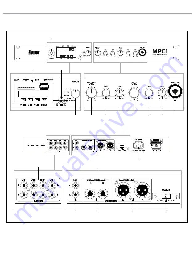
MPC1
12
15
16
17
13
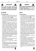
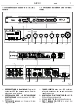
Front panel
Rear panel
1
5
7
6
8
10
11
9
M
4
3
2
14
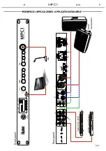
Fig.2
1.2 ELEMENTI DI COMANDO E DI COLLEGA-
MENTO
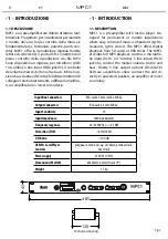
1.2 OPERATING ELEMENTS AND CONNEC-
TIONS
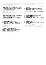
1.
INTERRUTTORE DI ACCENSIONE
dotato di
indicatore LED blu: quando acceso, l’unità è
alimentata correttamente
2.
INTERFACCIA PER LA RIPRODUZIONE
MULTIMEDIALE
tramite sorgente SD, USB e
Bluetooth
3.
PRESA JACK 3,5 mm
per l'ingresso di altre
sorgenti audio
1.
POWER SWITCH
with blue LED indicator:
when this indicator is on, the unit main power
supply is working
2.
MULTIMEDIA PLAYER INTERFACE
with SD,
USB and Bluetooth playback
3.
3,5 mm JACK PLUG
for other audio sources
4.
INPUT SIGNAL SELECTOR
to select the
LINE1/2/3/4/AUX 5


