


6
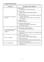
3.1 TROUBLE SHOOTING GUIDE
SYMPTOM
POSSIBLE CAUSE / REMEDY
1. After switch on, the power light
doesn't lit
A. NFB jumps off.
To check the main circuit-disconnect or short.
B. No power input.
To inspect the AC power input voltage and phase.
C. DC24V no output
(a) To inspect and make sure the switching power supply input
voltage is correct or not ?
(b) To Check the Fuse was burn down or not? If yes, please
replace new one.
D. Control PC board.
Please refer the item 2.
E. The indicator light breaks down.
(a) To make sure the voltage of indicator-DC24V.
(b) To inspect the indicator.
2. Control PC board indicator (LED
lamp) wasn't illuminated or
damaged.
A. AC or DC power input disconnected.
To inspect power input voltage and phase.
B. Fuse burn down.
To inspect the F1 & F2 fuse working or not, If damaged, please
replace a new one.
3. Inverter – no display.
A. Inverter has no power input.
Check if magnetic contactor is defective (replace).
B. Inverter has power input.
Check if inverter’s digital remote panel is defective (replace).
4. Inverter – displays ALM.
A. Inverter driver display" ALM "data.
To make sure the display status, and refer the inverter driver
Trouble shooting.
Summary of Contents for TR-3504
Page 2: ......
Page 8: ...T T TH H HI I IS S S P P PA A AG G GE E E I I IS S S B B BL L LA A AN N NK K K ...
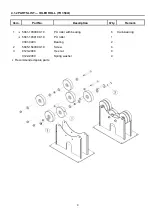
Page 11: ...3 1 3 INSTALLATION Power Roll Idler Roll ...
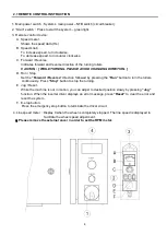
Page 13: ...5 2 1 REMOTE CONTROL INSTRUCTION ...
Page 19: ...11 T T TH H HI I IS S S P P PA A AG G GE E E I I IS S S B B BL L LA A AN N NK K K ...
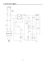
Page 20: ...12 5 1 CONTROL CIRCUIT 1ψ220V ...
Page 21: ...13 5 1 CONTROL CIRCUIT 3ψ380V 415V 460V ...
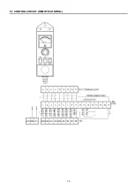
Page 22: ...14 5 1 CONTROL CIRCUIT REMOTE CONTROL ...
Page 23: ...15 5 2 CONTROL SYSTEM BOX 1ψ220V 3ψ380V 460V ...
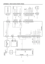
Page 26: ...18 APPENDIX B CIRCUIT AC220V 1 PHASE ...
Page 27: ...19 APPENDIX B CIRCUIT AC380 415V 460V 3 PHASE ...


