PRO1 Racing PRO1 2004 User Manual Download Page 2

Dear Customer

Enclosed you will find several data sheets and illustrations for the 2004 PRO1
race car.   All this data is based on what our factory engineers and drivers
have developed In design, testing and actual racing conditions. 

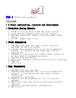
The PRO1 ¼ scale race car is a precision built machine.  For it to operate 
properly  the following must be adhered to:

-   Keep the car clean
-   Rebuild shocks every 3 to 4 races

-

Always check the suspension for free movement, replace damaged 
components.

-

Make sure servos and servo savers are functioning properly.  Never bottom
out servos at end points.

-

Tire maintenance is very important, all ways check for proper wear and loose
Bands.

-

Use a quality fuel such as VP16 and keep the air filter clean.

-

Do not over tighten the drive belt, make sure it has about ¼” deflection at
the center of the belt.

-

Have a check list that you can go by every time you put your PRO1 on the track

Sincerely

PRO1 Racing

118 E Swan Ave
Konawa, OK

  7

4849

580-320-7761

www.pro1z.com

Summary of Contents for PRO1 2004

Page 1: ...PRO1 2004 THE ULTIMATE RACING MACHINE...

Page 2: ...3 to 4 races Always check the suspension for free movement replace damaged components Make sure servos and servo savers are functioning properly Never bottom out servos at end points Tire maintenance...

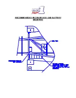
Page 3: ...RECOMMENEDED RECEIVER BOX AND BATTERY MOUNTING...

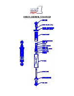
Page 4: ...SHOCK ASSEMBLY DIAGRAM...

Page 5: ...SPRING COLOR CODE AND RATES COLOR RATE in lb ORANGE 8 YELLOW 10 WHITE 14 SILVER 18 GREEN 20 BLUE 22 RED 31 BLACK 38...

Page 6: ...0 Rear tow right 1 8 tow in Front Camber left positive 2 degrees Front Camber right negative 2 degrees Rear Camber left positive 3 degrees Rear Camber right negative 4 degrees Shocks Front left red sp...

Page 7: ...ule measure at points A and shimming trailing arm pivot point until A points are1 8 towed in Use trailing arm pivot points for gross adjustments and rear links for fine adjustments When adjusting rear...

Page 8: ...LINKAGE AND CLUTCH HOUSING DIAGRAM FOR CARS BUILT AFTER TO 5 1 01 THE WY 16 1 OR WYK 32 CAN BE USED WITH THIS DESIGN WHEN USING THE WY 16 1 THE THROTTLE BARREL MUST BE ROTATED 180 DEG USE A FUTABA 33...

Page 9: ......

Page 10: ......

Page 11: ......

Page 12: ...MS ARE FACTORY SETTINGS AND ARE FOR YOUR REFERENCE RIGHT CASTER ANGLE IS 4 25 DEG LEFT CASTER ANGLE IS 3 50 DEG BOTH BEING POSITIVE A 1 32 INCH SPACER CHANGE WILL CHANGE THE CASTER ANGLE BY 75 DEG WHE...

Page 13: ...deg is the factory setting Increasing the angle will tighten the car up and decreasing the angle will loosen up the car Right Rear Right Rear 4 5 deg is the factory setting Increasing the Angle will...

Page 14: ...Right Front 2 5 deg is the factory setting Increasing The angle will cause the car to turn into the corner Decreasing the angle will cause the car to push Left Front Left Front 2 5 deg is the factory...

Page 15: ...frame impact resistant bumper design has a solid track record for protection of all critical components Precision components are CNC machined for accuracy interchangeability and structural integrity O...

Page 16: ...s with a variety of machined pistons o ring sealing and heavy duty rod end connections 3 Adjustable ride height with double shear connection at both ends of the shock absorbers 4 New steering rack des...

Page 17: ...s Camber Caster Toe front and rear Ride height Sway Bar Shock spring rate and oil viscosity This racing machine has a solid design foundation is fully adjustable and fun to race The PRO 1 PRO 1 is ava...

Page 18: ...NOTES Straight edge and alignment disk drawings...

Page 19: ...NOTES...

Page 20: ...NOTES...

Reviews: