PRO
WEL D
3 0 0 -0 8 0 5
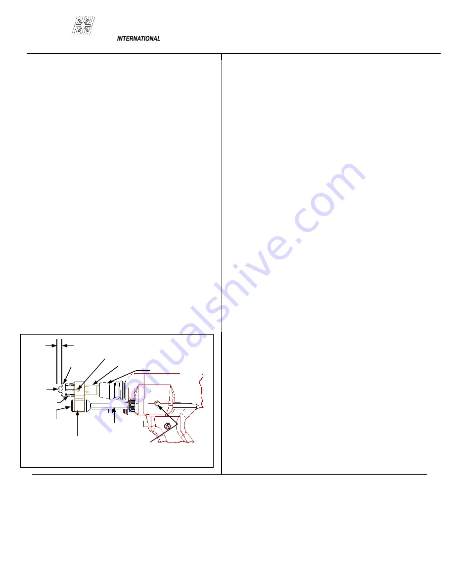
6.0 GUN SET-UP
The standard gun set-up is used for welding the ma-
jority of applications. It consists of the standard ad-
justable face plate, two legs, a foot, chuck adapter,
chuck, and spring for your specific stud size.
The following is a step by step explanation of the
correct way to set up the gun. (Refer to Figure 6-1)
1. A different, and correctly sized, chuck and ferrule
grip are needed for each different stud diameter and
style that will be welded. The appropriate chuck, or
stud holder, is inserted into the tapered chuck adapter
and tapped lightly to insure a tight fit. The ferrule
grip is inserted in the hole in the foot and secured
with the locking screws to hold it in place.
2. Studs must NOT bind or hang up on the foot, fer-
rule grip, or ferrule during the entire stud welding
process. To assure this, the foot/ferrule arrangement
must be centered in relation to the stud to be welded.
To assure centering, loosen the locking screws that
hold the foot to the legs. Place a stud in the chuck
and a ferrule in the grip. With the locking screw
loosened, the foot will move freely in all directions.
Adjust the foot so that the stud is centered in the fer-
rule and no contact occurs between the stud and the
ferrule during retraction or forward plunge of the stud.
Tighten the locking screws after centering the stud.
3. The “Plunge Length” is the amount of stud exposed
beyond the ferrule during initial set-up. Set the plunge
by loosening the leg adjusting screws and moving the
foot until the stud extends 1/8” to 3/16” past the end of
the ferrule. Tighten the leg adjusting screws after set-
ting the plunge and re-check centering to be sure the
stud is aligned properly in the ferrule.
4. The lift height, which determines the arc length,
has been pre-set at the factory and will automatically
lift and plunge the stud during the welding process.
“Lift” is the distance the gun will raise the stud above
the welding surface during the weld. This distance
governs the voltage and the arc. Improper lift will
cause unsatisfactory welds.
To measure the lift, turn the stud welding unit on and
set the timer to maximum time. (On certain units there
may be a Lift Check switch available, and in these
cases this switch can be used to check lift.) Trigger
the gun in the air or on a non-grounded or insulated
surface, to observe the lift cycle. Measuring the dis-
tance the stud or gun mechanism moves equals lift.
Usually this can be easily done by visual observation
or simple measurement against a static reference point
(i.e. the ferrule properly seated in the ferrule grip).
PAGE 3
Chuck Adaptor
Chuck
Locking Screws
Ferrule
Plunge Length
Stud
Ferrule Grip
(2) Foot
Screws
Foot
Leg
Leg Adj. Screw
Figure 6-1 GUN SET-UP
Summary of Contents for AG-805
Page 1: ...OPERATION MAINTENANCE MANUAL ...
Page 2: ......
Page 4: ...PRO WELD 300 0805 ...
Page 5: ...300 0805 PRO WELD ...
Page 6: ...PRO WELD 300 0805 ...
Page 7: ...300 0805 PRO WELD ...
Page 19: ...300 0805 PRO WELD ...


