background image

20

HOW TO USE THE MANUAL MODE

1.  Insert the key into the console.


See HOW TO TURN ON THE POWER on page 

18. Note: It may take a minute for the console to 

be ready for use.

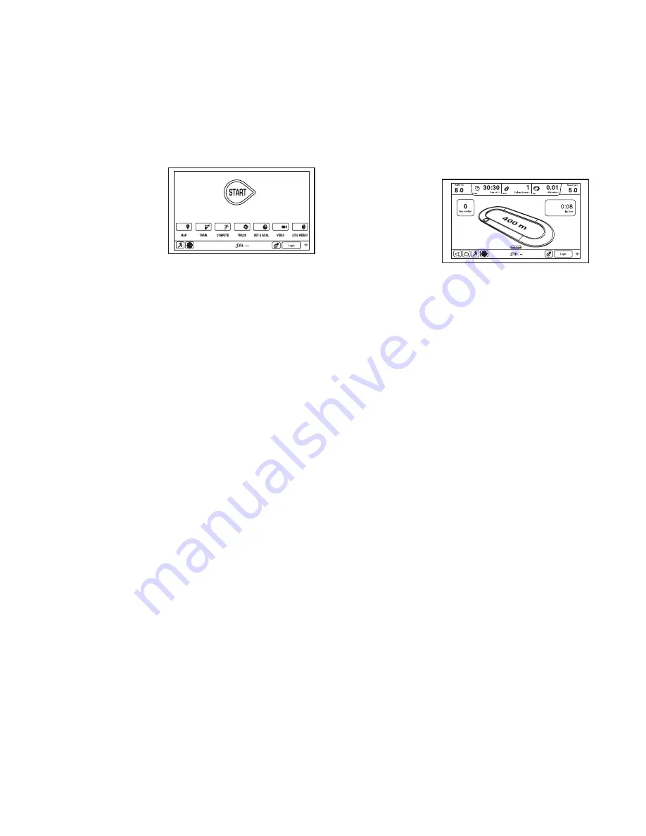
2.  Select the main menu.

   When you turn 

on the power, 

the main menu 

should appear 

after the 

console boots 

up. Touch the 

home button in 

the lower-left 

corner of the screen (not shown here) to return to 

the main menu at any time.

3.  Start the walking belt and adjust the speed.

   Touch the Start button on the screen or press the 

Start button on the console to start the walking 

belt. You can also press the Manual button on the 

console, and then touch the Resume button on the 

screen. The walking belt will begin to move at 1 

mph.

   As you exercise, change the speed of the walking 

belt as desired by pressing the Speed increase and 

decrease buttons. Each time you press one of the 

buttons, the speed setting will change by 0.1 mph; 

if you hold down the button, the speed setting will 

change in increments of 0.5 mph. 

   If you press one of the numbered Quick Speed but-

tons, the walking belt will gradually change speed 

until it reaches the selected speed setting.

   To select a speed setting that includes a decimal—

such as 3.5 mph—press two numbered buttons in 

succession. For example, to select a speed setting 

of 3.5 mph, press the 3 button and then immedi-

ately press the 5 button. Note: This will not function 

if the console is set to metric units.

   To stop the walking belt, press the Stop button. To 

restart the walking belt, press the Start button.

4.   Change the incline of the treadmill as desired.

   To change the incline of the treadmill, press the 

Incline/Decline increase and decrease buttons or 

one of the numbered Quick Incline/Decline buttons. 

Each time you press one of the buttons, the incline 

will gradually change until it reaches the selected 

incline setting.

   Note: The first time you adjust the incline, you must 

first calibrate the incline system (see step 4 on 

page 26).

5.  Monitor your progress.


 The  console 

offers sev-

eral display 

modes. The 

display mode 

that you select 

will determine 

which workout 

information is shown. To select the desired display 

mode, simply flick or slide the screen. You can also 

view additional information by touching the red 

boxes on the screen. 

   As you walk or run on the treadmill, the screen can 

show the following workout information:

  •  The incline level of the treadmill

  •  The time elapsed

  •   The time left (Note: The manual mode does not 

have a time left countdown.)

  •   The approximate number of calories you have 

burned 

  •   The approximate number of calories you are 

burning per hour

  •  The distance that you have walked or run

  •  The number of vertical feet you have climbed

  •   The speed of the walking belt 

  •  A track representing 1/4 mile (400 m)

  •  Your pace in minutes per mile

  •  Your current lap number

  •  Your heart rate (see step 6)

Summary of Contents for PFTL16011.0

Page 1: ...nual for future reference QUESTIONS If you have questions or if parts are damaged or missing DO NOT CONTACT THE STORE please contact Customer Care IMPORTANT Please register this product see the limited warranty on the back cover of this manual before contacting Customer Care CALL TOLL FREE 1 888 533 1333 Mon Fri 6 a m 6 p m MT Sat 8 a m 4 p m MT ON THE WEB www proformservice com www proform com US...

Page 2: ...RDERING REPLACEMENT PARTS Back Cover LIMITED WARRANTY Back Cover This drawing shows the locations of the warning decals If a decal is missing or illegible call the telephone number on the front cover of this manual and request a free replacement decal Apply the decal in the location shown Note The decals may not be shown at actual size WARNING DECAL PLACEMENT 310841 PROFORM is a registered tradema...

Page 3: ...nto the surge suppressor or into an outlet on the same circuit 12 Use only a surge suppressor that meets all of the specifications described on page 16 To purchase a surge suppressor see your local PROFORM dealer call the telephone number on the front cover of this manual or see your local electronics store 13 Failure to use a properly functioning surge suppressor could result in damage to the con...

Page 4: ...n 23 Never insert any object into any opening on the treadmill 24 Inspect and properly tighten all parts of the treadmill regularly 25 DANGER Always unplug the power cord immediately after use before clean ing the treadmill and before performing the maintenance and adjustment procedures described in this manual Never remove the motor hood unless instructed to do so by an authorized service represe...

Page 5: ... If you have questions after reading this manual please see the front cover of this manual To help us assist you please note the product model number and serial number before contacting us The model number and the location of the serial num ber decal are shown on the front cover of this manual Before reading further please review the drawing below and familiarize yourself with the labeled parts BE...

Page 6: ...r Washer 14 4 3 8 x 1 Bolt 6 4 3 8 x 1 Flat Head Bolt 15 4 PART IDENTIFICATION CHART Use the drawings below to identify small parts used for assembly The number in parentheses below each draw ing is the key number of the part from the PART LIST near the end of this manual The number following the key number is the quantity used for assembly Note If a part is not in the hardware kit check to see if...

Page 7: ...ove the packing materials Do not dispose of the packing materials until you finish all assembly steps The underside of the walking belt is coated with high performance lubricant After shipping there may be some lubricant on top of the walking belt or on the shipping carton This is normal If there is lubricant on top of the walking belt wipe it off with a soft cloth and a mild non abrasive cleaner ...

Page 8: ... Upright Wire 88 Then pull the other end of the wire tie until the Upright Wire is routed through the Left Upright 88 3 88 90 Wire Tie Wire Tie 90 105 88 2 Pull the Upright Wire 88 and the base ground wire A through the indicated hole in the Base 105 Attach the base ground wire A to the Base 105 with a 8 x 1 2 Ground Screw 10 Press the Grommet 101 into the square hole in the Base 105 88 2 Hole 10 ...

Page 9: ...se ground wire A in the hole in the side of the Left Upright Insert two 3 8 x 2 3 4 Screws 8 and two 3 8 x 1 1 4 Screws 9 with two 3 8 Star Washers 14 into the Left Upright Partially tighten the 3 8 x 2 3 4 Screws 8 and the 3 8 x 1 1 4 Screws 9 until the heads of the Screws touch the Left Upright 90 do not fully tighten the Screws yet Note It may be help ful to use the Short Hex Key 43 on the Scre...

Page 10: ...Handrail Brackets 89 Then remove the Handrail Brackets from the Left and Right Handrails 92 93 The Screws and Star Washers will be used in step 8 6 14 6 6 14 89 8 Identify the Left and Right Handrails 92 93 Hold the Left Handrail 92 near the Left Upright 90 Insert the Upright Wire 88 into the large hole in the bottom of the Left Handrail and out of the front of the Left Handrail Slide the Left Han...

Page 11: ...to pinch the pulse wire against the pulse assembly Attach the pulse assembly with four 10 x 3 4 Screws 3 and four 10 Star Washers 11 Start all four Screws and then tighten them 10 11 Set the console assembly face down on a soft surface to avoid scratching the console assembly Identify the Left and Right Trays 110 111 Attach the Trays 110 111 to the console assembly with six 8 x 1 2 Screws 1 Start ...

Page 12: ...ld the con sole assembly near the Uprights 90 99 Connect the Upright Wire 88 to the console wire See the inset drawing The connectors should slide together easily and snap into place If they do not turn one connector and try again IF YOU DO NOT CONNECT THE CON NECTORS PROPERLY THE CONSOLE MAY BECOME DAMAGED WHEN YOU TURN ON THE POWER Next connect the two pulse wires Then remove the wire tie from t...

Page 13: ... Attach the other Tray Bracket not shown to the Left Upright not shown in the same way Attach the Tray 87 to the Tray Brackets 91 with four 8 x 3 4 Screws 2 only one side is shown Start all four Screws and then tighten them 91 2 14 87 99 16 Raise the Frame 64 to the position shown Have a second person hold the Frame until this step is completed Orient the Storage Latch 65 so that the large barrel ...

Page 14: ...ainst the Frame 18 64 69 41 17 Attach the upper end of the Storage Latch 65 to the Frame 64 with a 3 8 x 1 3 4 Bolt 7 and a 3 8 Nut 13 17 65 13 64 7 19 Make sure that all parts are properly tightened before you use the treadmill If there are sheets of plastic on the treadmill decals remove the plastic To protect the floor or carpet place a mat under the treadmill Note Extra hardware may be include...

Page 15: ...tures above 122 F 50 C or below 14 F 10 C Do not excessively bend or stretch the sensor when using or storing the heart rate monitor To clean the sensor use a damp cloth and a small amount of mild soap Then wipe the sensor with a damp cloth and thoroughly dry it with a soft towel Never use alcohol abrasives or chemicals to clean the sensor Hand wash and air dry the chest strap TROUBLESHOOTING If t...

Page 16: ...d into a surge suppressor and plug the surge suppressor into an appropriate outlet that is properly installed and grounded in accordance with all local codes and ordinances The outlet must be on a nominal 120 volt circuit capable of carrying 15 or more amps To avoid overloading the circuit do not plug other electrical devices except for low power devices such as cell phone chargers into the surge ...

Page 17: ...tically controls the speed and incline of the treadmill as it guides you through an effective exercise session In addition you can set a calorie time distance or pace goal When you use the manual mode you can change the speed and incline of the treadmill with the touch of a button As you exercise the console will display instant exer cise feedback You can also measure your heart rate using the han...

Page 18: ...ake a minute for the console to be ready for use HOW TO USE THE TOUCH SCREEN The console features a tablet with a full color touch screen The following information will help you become familiar with the tablet s advanced technology The console functions similarly to other tablets You can slide or flick your finger against the screen to move certain images on the screen such as the displays in a wo...

Page 19: ...address Enter the activation code from the iFit Live flier that came with the treadmill Touch the Place of Purchase drop down menu for a list of options then touch the location where you pur chased your product Touch the words MEDICAL DISCLAIMER read the medical disclaimer touch the I Accept button and check the medi cal disclaimer checkbox Then touch the Confirm Activation Code button Enter the r...

Page 20: ... then immedi ately press the 5 button Note This will not function if the console is set to metric units To stop the walking belt press the Stop button To restart the walking belt press the Start button 4 Change the incline of the treadmill as desired To change the incline of the treadmill press the Incline Decline increase and decrease buttons or one of the numbered Quick Incline Decline buttons E...

Page 21: ...urn on the fan if desired The fan features multiple speed settings and an auto mode When the auto mode is selected the speed of the fan will automatically increase and decrease as the speed of the walking belt increases and decreases Press the Fan increase button to increase the fan speed Note If you press the Fan increase button once while the fan is on its maximum speed set ting the auto fan mod...

Page 22: ...d and or incline settings for the next segment The workout will continue in this way until the last segment ends The walking belt will then slow to a stop and a workout summary will appear on the screen After you view the workout summary touch the Finish button to return to the main menu You may also be able to either save or publish your results using one of the options on the screen If the speed...

Page 23: ...A moment after you touch the button the walking belt will begin to move Hold the handrails and begin walking The workout will function in the same way as the manual mode see pages 20 and 21 The workout will continue until you reach the goal that you set The walking belt will then slow to a stop and a workout summary will appear on the screen After you view the workout summary touch the Finish butt...

Page 24: ...ress one of the iFit Live buttons on the console To switch users within the account touch the user button near the lower right corner of the screen Before some workouts will download you must add them to your schedule on iFit com For more information about the iFit Live work outs please see www iFit com When you select an iFit Live workout the screen will show the name duration and distance of the...

Page 25: ...ch into the reset position and insert the key into the console However when you remove the key the screen will show a demo presentation To turn on or turn off the display demo mode first touch the Demo Mode button Next touch the On checkbox or the Off checkbox Then touch the back button on the screen 6 Enable or disable the key Note This feature may not be enabled on your treadmill You can disable...

Page 26: ...ug it into the USB port on the side of the console The update should begin automatically The screen will show the progress of the update When the update is complete the treadmill will turn off and then turn back on If it does not press the power switch into the off position Wait for several seconds and then press the power switch into the reset position Note It may take a few minutes for the conso...

Page 27: ...know your network name SSID If your network has a password you will also need to know the password An information box will ask if you want to connect to the wireless network Touch the Connect button to connect to the network or touch the Cancel but ton to return to the list of networks If the network has a password touch the password entry box A keyboard will appear on the screen To view the passw...

Page 28: ...it is already moving at 2 mph or slower A countdown of three minutes will begin after which the walking belt will slow to a stop HOW TO USE THE INTERNET BROWSER Note To use the browser you must have access to a wireless network including an 802 11b n router with SSID broadcast enabled hidden networks are not supported To open the browser touch the globe button near the lower left corner of the scr...

Page 29: ... the treadmill may require two people 1 Hold the frame and one of the handrails and place one foot against a wheel 2 Pull back on the handrail until the treadmill will roll on the wheels and carefully move it to the desired location CAUTION Do not move the tread mill without tipping it back do not pull on the frame and do not move the treadmill over an uneven surface 3 Place one foot against a whe...

Page 30: ...en press the switch back in SYMPTOM The power turns off during use a Check the power switch see the drawing above If the switch has tripped wait for five minutes and then press the switch back in b Make sure that the power cord is plugged in If the power cord is plugged in unplug it wait for five minutes and then plug it back in c Remove the key from the console and then reinsert it d If the tread...

Page 31: ...s overtightened treadmill per formance may decrease and the walking belt may become damaged Remove the key and UNPLUG THE POWER CORD Using the hex key turn both idler roller screws counterclockwise 1 4 of a turn When the walking belt is properly tightened you should be able to lift each edge of the walking belt 2 to 3 in 5 to 7 cm off the walking platform Be careful to keep the walking belt center...

Page 32: ...er roller screws clockwise 1 4 of a turn When the walk ing belt is correctly tightened you should be able to lift each edge of the walking belt 2 to 3 in 5 to 7 cm off the walking platform Be careful to keep the walking belt centered Then plug in the power cord insert the key and carefully walk on the treadmill for a few minutes Repeat until the walk ing belt is properly tightened SYMPTOM The iFit...

Page 33: ...ic Exercise If your goal is to strengthen your cardiovascular system you must perform aerobic exercise which is activity that requires large amounts of oxygen for prolonged periods of time For aerobic exercise adjust the intensity of your exercise until your heart rate is near the highest number in your training zone WORKOUT GUIDELINES Warming Up Start with 5 to 10 minutes of stretch ing and light...

Page 34: ... 44 1 Left Frame Cap 45 1 Left Foot Rail 46 8 Platform Bracket 47 1 Left Foot Rail Base 48 1 Left Frame Cover 49 1 Idler Roller 50 1 Right Frame Cap 51 1 Walking Belt 52 2 Platform Cushion Bracket 53 1 Walking Platform 54 2 Platform Cushion 55 2 Belt Guide 56 2 Front Cushion 57 1 Reed Switch Clamp 58 1 Magnet 59 1 Reed Switch 60 4 Wire Tie 61 1 Drive Roller Pulley 62 1 Right Foot Rail 63 1 Right F...

Page 35: ... Audio Wire 110 1 Left Tray 111 1 Right Tray 112 1 Console 113 1 Console Frame 114 4 Console Clamp 115 1 Console Ground Wire 116 6 Cable Tie 117 1 Right Handrail Cover 118 1 Left Handrail Cover 119 1 Right Wheel Cap User s Manual Note Specifications are subject to change without notice For information about ordering replacement parts see the back cover of this manual These parts are not illustrate...

Page 36: ...63 62 56 44 46 47 45 46 46 46 46 56 69 50 29 29 29 29 29 29 37 37 29 37 70 16 69 19 71 37 37 37 46 46 48 46 70 40 40 40 40 40 2 2 16 16 41 40 41 37 40 37 40 54 54 52 30 30 52 30 42 43 19 19 19 19 16 16 16 16 16 29 37 37 17 19 33 37 39 16 16 16 30 30 16 16 16 30 30 30 16 95 EXPLODED DRAWING A Model No PFTL16011 0 R1211A ...

Page 37: ...37 73 10 80 81 82 2 10 2 2 79 36 75 74 77 21 36 76 74 77 72 22 35 35 78 82 2 2 84 15 15 83 38 2 2 2 16 16 2 38 38 EXPLODED DRAWING B Model No PFTL16011 0 R1211A ...

Page 38: ...88 96 97 16 9 2 36 10 94 94 16 16 16 36 36 8 8 94 91 91 87 104 34 104 34 102 89 89 85 86 93 92 98 2 2 3 11 3 11 14 6 15 14 15 14 14 6 12 4 12 14 6 6 14 15 14 8 2 2 2 2 2 4 100 100 102 119 118 117 2 2 EXPLODED DRAWING C Model No PFTL16011 0 R1211A ...

Page 39: ...39 106 107 1 1 113 2 1 1 2 2 10 115 20 114 20 20 112 2 2 108 1 1 111 2 110 2 20 2 1 2 2 109 114 114 114 116 116 EXPLODED DRAWING D Model No PFTL16011 0 R1211A ...

Page 40: ...ght damage to the product This warranty will automatically be voided if the product is used as a store display model if the product is purchased or transported outside the USA if all instructions in this manual are not followed if the product is abused or improperly or abnormally used or if the product is used for commercial or rental purposes No other warranty beyond that specifically set forth a...

Reviews: