background image

15

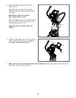
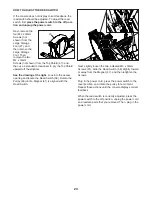
   To vary the motion of the pedals, you can change 

the incline of the frame. To change the incline,  

press the Incline increase and decrease buttons.

   Note: After you press a button, it will take a 

moment for the frame to reach the selected incline 

level. 

5.   Do interval training, if desired.

   As you exercise, you can alternate between 

intervals of low-intensity (recovery) exercise 

and intervals of high-intensity (work) exercise, if 

desired.

   To create a recovery interval, first adjust the 

resistance of the pedals to the desired level. Then, 

press and hold the Recovery button until two tones 

sound to save the interval setting.

   To create a work interval, first adjust the resistance 

of the pedals to the desired level. Then, press and 

hold the Work button until two tones sound to save 

the interval setting.

   As you exercise, press the Recovery and Work 

buttons as desired to alternate between the saved 

interval settings. After you press a button, the resis-

tance of the pedals will automatically adjust to the 

level that you saved.

   To change the interval settings at any time during 

your workout, simply repeat this step.

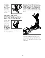
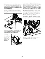
6.   Follow your progress with the power ring, and 

set a power output target, if desired.

   The power ring 

will provide a 

visual representa-

tion of your power 

output in watts 

per kilogram of 

body weight. As 

your power out-

put increases or 

decreases, a solid 

bar will appear or 

disappear in the 

power ring.


To set a power output target, press the Watts 

increase and decrease buttons until the desired 

power output target appears in the display. 

   Note: After you set a power output target, the 

resistance level will automatically adjust to a preset 

level. You can manually override the preset level at 

any time.

   If you set a power output target during the 

manual mode, a flashing indicator will appear in 

the power ring to indicate your power output target. 

As you exercise, adjust your pedaling speed or the 

resistance of the pedals to keep your power output 

near the power output target.

   To change the power output target at any time 

during your workout, simply repeat the actions 

above.

   IMPORTANT: The power output target is 

intended only to provide motivation. Make sure 

to pedal at a speed and a resistance level that 

is comfortable for you.


During an onboard workout, the power ring will 

show the preset power output target for each seg-

ment of the workout (see step 4 on page 18).

Solid Bar

Power Output 

Target

Actual Power 

Output

Summary of Contents for PFEVEL80717.0

Page 1: ...or future reference CUSTOMER SERVICE UNITED KINGDOM Call 0330 123 1045 From Ireland 053 92 36102 Website iconsupport eu E mail csuk iconeurope com Write ICON Health Fitness Ltd Unit 4 Westgate Court S...

Page 2: ...the front cover of this manual and request a free replacement decal Apply the decal in the location shown Note The decal s may not be shown at actual size TABLE OF CONTENTS PROFORM and IFIT are regist...

Page 3: ...side To protect the floor or carpet from dam age place a mat under the elliptical 8 Inspect and properly tighten all parts each time the elliptical is used Replace any worn parts immediately 9 Keep ch...

Page 4: ...trends in general 19 The elliptical does not have a freewheel the pedals will continue to move until the fly wheel stops Reduce your pedaling speed in a controlled way 20 Keep your back straight whil...

Page 5: ...more effective and enjoyable For your benefit read this manual carefully before you use the elliptical If you have questions after reading this manual please see the front cover of this manual To help...

Page 6: ...ping supports attached to the rear of the Frame 1 remove the screws attach ing the shipping supports Discard the screws and the shipping supports Attach the Rear Stabilizer 70 to the Frame 1 with two...

Page 7: ...ed to the front of the Frame 1 remove the screws attach ing the shipping supports Discard the screws and the shipping supports Attach the Front Stabilizer 73 to the Frame 1 with two M10 x 120mm Screws...

Page 8: ...ard and turn it so that it is flush with the Right Leg Front and Rear Covers 11 15 Repeat this step on the other side of the elliptical 5 7 Make sure that all parts of the elliptical are properly tigh...

Page 9: ...ug the indicated end of the power cord into the socket on the frame 2 Plug the power cord into an appropriate outlet that is properly installed and earthed in accordance with all local codes and ordin...

Page 10: ...y arms Next hold the handle E on the front stabilizer and lift the elliptical until it will roll on the wheels not shown on the rear stabilizer Then carefully move the elliptical to the desired locati...

Page 11: ...sired angle Reverse these actions to remove the tablet from the tablet holder HOW TO EXERCISE ON THE ELLIPTICAL To mount the elliptical hold the handlebars I or the upper body arms J and step onto the...

Page 12: ...shown on the front stabilizer and lift the elliptical to the upright position so that it is resting on the small L and large storage feet M See the lower drawing To lower the elliptical for use first...

Page 13: ...blet to the console and use the iFit Bluetooth Tablet app to record and track your workout information The console also offers a selection of onboard work outs Each onboard workout automatically chang...

Page 14: ...THE MANUAL MODE 1 Begin pedaling or press any button on the console to turn on the console See HOW TO TURN ON THE POWER at the left 2 Select the manual mode When you turn on the console the manual mo...

Page 15: ...low your progress with the power ring and set a power output target if desired The power ring will provide a visual representa tion of your power output in watts per kilogram of body weight As your po...

Page 16: ...out information in a repeating cycle To select the scan mode press the Display button repeatedly until the word SCAN appears in the display Change the volume level of the console by pressing the Vol...

Page 17: ...as several speed set tings Press the Fan increase and decrease buttons repeat edly to select a fan speed or to turn off the fan Note If the pedals do not move for about thirty seconds the fan will tur...

Page 18: ...end of each segment of the workout a series of tones will sound The resistance level for the next segment will appear in the display for a few seconds to alert you The resistance of the pedals will th...

Page 19: ...audio cable see your local electronics store Next press the play button on your personal audio player Adjust the volume level using the Vol increase and decrease buttons on the con sole or the volume...

Page 20: ...ole will turn solid blue 4 Record and track your workout information Follow the instructions in the iFit Bluetooth Tablet app to record and track your workout information 5 Disconnect your tablet from...

Page 21: ...w weight pedaling speed and distance in standard or met ric units of measurement An E for English miles or an M for metric kilometers will appear in the display To change the unit of measure ment pres...

Page 22: ...rate when you hold the handgrip heart rate monitor or if the dis played heart rate appears to be too high or too low see step 8 on page 16 HOW TO CALIBRATE THE INCLINE SYSTEM If the incline system is...

Page 23: ...liptical See the drawing at the right Look into the access opening and locate the Reed Switch 58 Rotate the Pulley 66 until a Magnet 41 is aligned with the Reed Switch Next slightly loosen the two ind...

Page 24: ...left Remove the four M4 x 16mm Screws not shown from the Large Storage Foot 27 and then remove the Large Storage Foot Remove the two M4 x 16mm Screws not shown from the Top Shield 37 and use a standar...

Page 25: ...c Exercise If your goal is to strengthen your cardiovascular system you must perform aerobic exercise which is activity that requires large amounts of oxygen for prolonged periods of time For aerobic...

Page 26: ...lles Stretch With one leg in front of the other reach forward and place your hands against a wall Keep your back leg straight and your back foot flat on the floor Bend your front leg lean forward and...

Page 27: ...1 Right Pedal Arm 50 2 Small Wheel 51 2 Small Storage Foot 52 1 Idler 53 1 Small Spacer 54 1 Resistance Motor 55 2 Axle Cover 56 4 M4 x 12mm Washer Head Screw 57 1 Clamp 58 1 Reed Switch Wire 59 2 M10...

Page 28: ...Locknut 118 1 M6 x 16mm Screw 119 1 Right Pedal Pad 120 1 Left Pedal Pad 121 1 Right Pedal Handle 122 1 Left Pedal Handle 123 1 Right Pedal Plate 124 1 Left Pedal Plate 125 1 Lift Motor Axle 126 2 Spr...

Page 29: ...6 48 50 52 47 51 42 54 25 58 59 59 53 61 57 60 60 56 61 66 61 70 72 71 71 74 74 103 130 103 79 79 77 83 83 82 82 61 107 100 91 115 106 84 96 68 98 99 97 99 99 73 84 109 84 77 99 61 112 112 55 105 118...

Page 30: ...101 6 8 10 10 12 120 124 122 9 11 14 18 19 127 98 126 116 117 128 121 123 15 17 17 20 20 23 23 30 32 22 29 29 31 39 33 33 61 61 61 49 76 61 61 76 33 33 76 78 81 81 92 95 75 3 5 2 16 21 61 61 61 62 67...

Page 31: ...31 26 26 27 36 36 37 45 44 113 113 113 113 113 113 61 61 61 61 61 61 61 61 61 61 61 64 64 64 64 64 64 65 35 65 65 34 65 111 132 65 65 65 61 61 113 113 EXPLODED DRAWING C Model No PFEVEL80717 0 R0517A...

Page 32: ...T and the EXPLODED DRAWING near the end of this manual ORDERING REPLACEMENT PARTS This electronic product must not be disposed of in municipal waste To preserve the environment this product must be re...

Reviews: